Torque crossmember

a crossmember and torque technology, applied in the field of crossmembers, can solve the problems of increased cost and installation expenditure, unsatisfactory deformation, comparatively complicated, etc., and achieve the effects of improving the rigidity of the crossmember, reducing the cost of installation, and increasing the compressive for

Inactive Publication Date: 2007-05-17
ISE INNOMOTIVE SYST EURO
View PDF8 Cites 10 Cited by
  • Summary
  • Abstract
  • Description
  • Claims
  • Application Information

AI Technical Summary

Benefits of technology

[0021] The utilization of a hollow chamber profile that is essentially realized in one piece with the supporting device and arranged in the region of load introduction points makes it possible to transmit the introduced forces to the mounting flanges within the crossmember profile, namely without having to transmit the torsional forces via joint seams. The one or more hollow chamber profiles preferably has / have an essentially closed cross section. This makes it possible to advantageously improve the rigidity of the crossmember because closed profile cross sections are able to support higher compressive forces in the longitudinal direction of the profile than open profile cross sections.
[0022] It is also particularly advantageous to realize the crossmember profile or the one or more hollow chamber profiles of the crossmember in the form of extruded profiles, particularly extruded aluminum profiles, because a weight advantage can be achieved with this measure in addition to or independently of the advantages attained with the embossment or the arrangement of a central web or web within the crossmember profile. It is not only possible to vary the wall thickness of at least one hollow chamber profile, but also the wall thickness of individual areas of a hollow chamber profile. This allows a particularly simple adaptation of the crossmember rigidity in the area of the load introduction points.
[0023] Due to the embossments, it is not required to weld on additional components in the area of the load introduction point as it is the case, for example, with the supporting bearing in DE 102 06 472 A1 such that the structure of the inventive crossmember profile is not weakened due to the application of heat occurring during the welding process. According to the invention, the realization of an embossment or embossments provides a safe, simple and simultaneously cost-efficient method for increasing the rigidity, the advantages of which become particularly apparent in the manufacture of larger quantities of crossmembers.
[0024] It is furthermore advantageous to realize the device for introducing torsional forces in the form of an essentially flat element or in the form of a frame-shaped supporting device that is realized in one piece with the crossmember or can be mounted thereon. In contrast to a more massive construction with sheet metal parts, a frame-shaped supporting device makes it possible to reduce the weight. It is advantageous to provide at least one supporting element for obliquely supporting the frame-shaped device relative to the crossmember such that a particularly high rigidity of the crossmember can also be achieved in this lower region. Compressive forces occurring in the lower region of the crossmember can be supported very well in this fashion. The crossmember profile and / or the supporting element is / are advantageously realized in the form of an extruded component. This allows a simple manufacture that is also very economical because it is not excessively time-consuming. In order to additionally reduce the costs, the supporting elements may be cut off in the end regions at approximately identical angles such that they can be mounted on the crossmember and on the frame-shaped supporting device in a laterally reversed fashion. However, in irregularly shaped crossmembers, the supporting elements naturally are adapted to the extent of the crossmember and the frame-shaped supporting device(s) is / are adapted to the crossmember in order to ensure an optimal support of the frame-shaped supporting device relative to the crossmember.
[0025] It is advantageous to provide at least one reinforcing element for being inserted into an angular region of the crossmember. This measure makes it possible to also reinforce the crossmember in other regions, particularly with respect to compressive forces. Such a reinforcing element proves particularly advantageous for preventing the undesirable buckling of the crossmember in regions of the longitudinal extent of the crossmember in which the bending angles are smaller.

Problems solved by technology

However, the arrangement of the supporting bearing on the crossmember may lead to an undesirable deformation thereof when a force is introduced.
This design is comparatively complicated and therefore associated with increased costs and installation expenditures.
The above-described known torsional support devices for engines are composed of various parts and therefore associated with high installation and manufacturing expenditures, as well as subject to the risk of twisting the crossmember if higher forces are introduced, namely despite the devices for increasing the rigidity that are provided in some of the described arrangements.

Method used


Image

  • Torque crossmember
  • Torque crossmember
  • Torque crossmember

Examples


Embodiment Construction

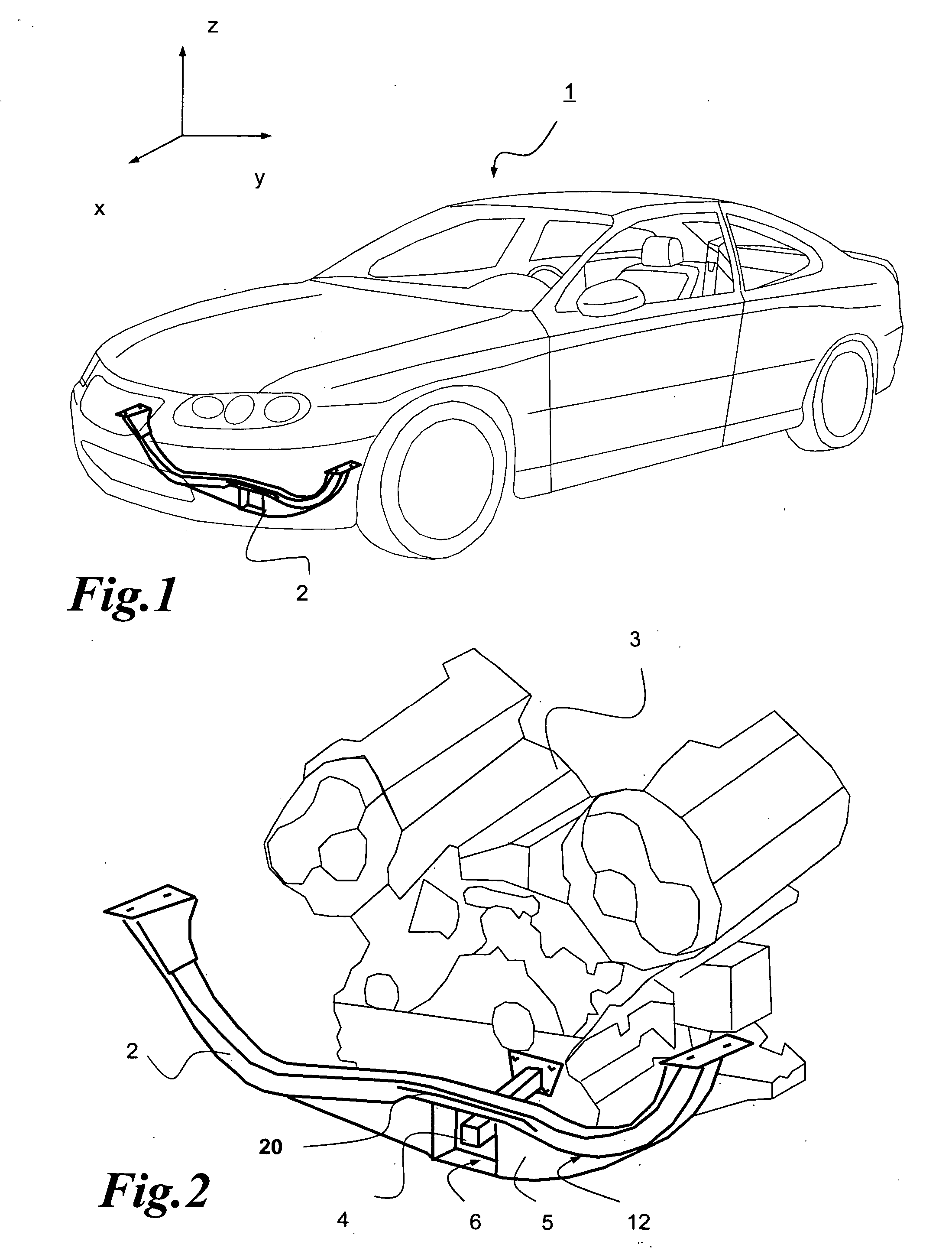
[0039]FIG. 1 shows a perspective representation of a vehicle 1 having a crossmember 2 for supporting torsional forces in its front area. The crossmember is arranged in the front area of the vehicle engine compartment. It serves for supporting torsional forces that are introduced into the crossmember along the three spatial axes, e.g., in the Z-direction, such that a tilting motion of the engine can take place along the three spatial axes, e.g., along the Y-axis, under certain driving conditions, wherein this tilting motion can be limited with the aid of the crossmember.

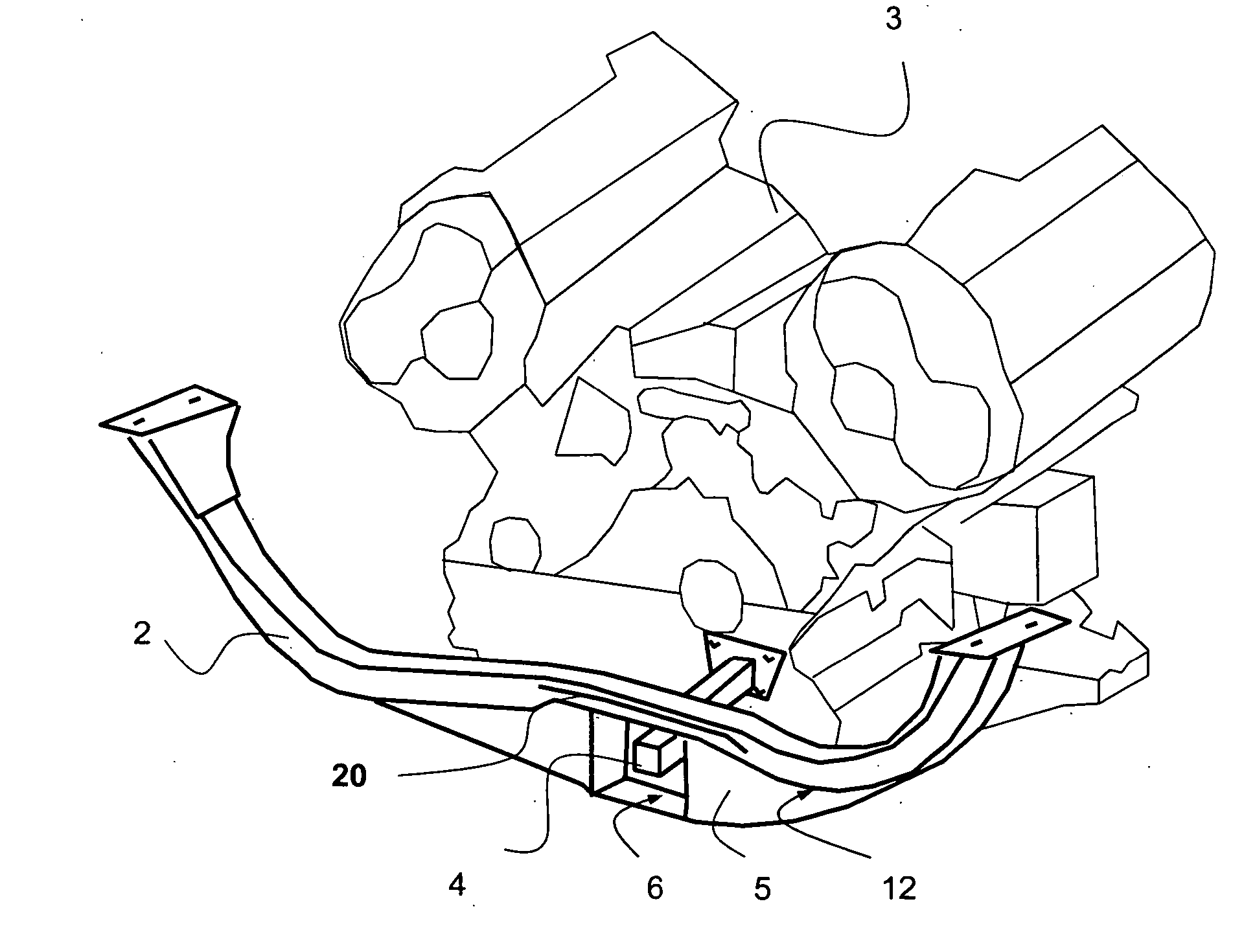
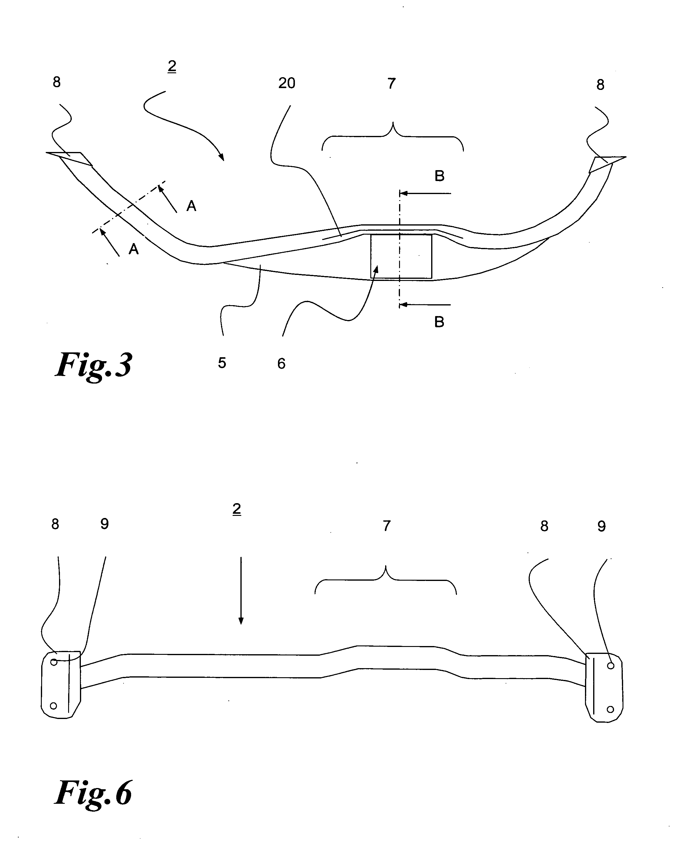
[0040]FIG. 2 shows a detail of an engine unit 3 arranged in the engine compartment of the vehicle 1 and better elucidates how a torque bracket 4 protrudes into the crossmember through an opening 6 in a supporting device 5. The supporting device is arranged on the underside 12 of the crossmember. The crossmember 2 is realized in an approximately W-shaped fashion in a side view, wherein the supporting device is arrange...


PUM


Abstract

A crossmember for supporting and limiting torsional forces of an engine unit relative to a mounting frame, particularly a vehicle body, wherein the crossmember is provided with at least one area or one device for introducing torsional forces into the crossmember.

Description

FIELD OF THE INVENTION [0001] The invention pertains to a crossmember for supporting and limiting torsional forces of an engine unit relative to a mounting frame, particularly a vehicle body, wherein the crossmember is provided with at least one area or one device for introducing torsional forces into the crossmember. BACKGROUND OF THE INVENTION [0002] Crossmembers of this type are known from the state of the art. They are usually arranged in the front region of an engine compartment of a motor vehicle and serve for supporting the torsional forces introduced by the engine. This is intended to limit or absorb the tilting motion of the engine that is caused by the torsional forces under certain driving conditions. [0003] A crossmember of this type is known, e.g., from DE 102 06 472 A1, wherein a crossmember with the approximate shape of a U in a side view is provided with a supporting bearing that is mounted on the upper side of the crossmember, i.e., in the region of the opening of t...

Claims


Application Information

Patent Timeline
Patent Type & Authority Applications(United States)
IPC IPC(8): B62D25/08
CPCB62D21/11B62D25/082
Inventor GUNTHER, STEFANSTEFFENS, HUBERTUS
Owner ISE INNOMOTIVE SYST EURO
Why Eureka
Try Eureka