Application of a switched reluctance motion control system in a chiller system

a technology of motion control and switched reluctance, which is applied in the direction of motor/generator/converter stopper, dynamo-electric converter control, etc., can solve the problems of motors that require their own controller or electronic drive, e.g., switched reluctance motors, and cannot be used in chiller systems. , to achieve the effect of improving system efficiency, reducing operating temperatures, and improving overall system efficiency

Inactive Publication Date: 2007-05-17
JOHNSON CONTROLS TYCO IP HLDG LLP
View PDF14 Cites 34 Cited by
  • Summary
  • Abstract
  • Description
  • Claims
  • Application Information

AI Technical Summary

Benefits of technology

[0012] One advantage of the present invention is improved overall system efficiency through lower operating temperatures in the motor and VSD, from the use of condenser water to cool the components.
[0013] Another advantage of the present invention is increased system efficiency and potential cost reduction by eliminating gears between the motor and the compressor.
[0014] A further advantage of the present invention is improved reliability of the chiller system due to the robust design of the switched reluctance motor.
[0015] Still another advantage of the present invention is improved system efficiency realized through reduced windage and friction losses in the motor.
[0016] A further advantage of the present invention is a higher maximum operating speed and a faster dynamic response of the motor.

Problems solved by technology

The use of line voltages and frequencies typically required the compressors to use some inefficient mechanical means (such as inlet guide vanes for centrifugal compressors and a slide valve for screw compressors) for modulating capacity as a result of the motor being limited to one operating speed that was based on the input frequency to the motor.
Furthermore, motors that required their own controller or electronic drive, e.g., switched reluctance motors, could not be used for these chiller systems, as such motors could not operate directly from standard (main) voltages and frequencies.
One limitation of prior induction motor style VSDs is that the magnitude of the output voltage from the VSD can be no larger than the magnitude of the input, or utility, line voltage to the VSD.
This limitation on the output voltage of the variable speed drive limits the maximum speed of the conventional induction motor to a speed that corresponds to the speed of the motor operated at line voltage (because of the constant volts / hertz ratio required by a conventional induction motor).
In addition, this limitation on the output voltage from the VSD limits the operating speed range of high-speed motors, including high-speed switched reluctance motors, in the chiller system.
The high speed motors, used to obtain faster compressor speeds without the “step up” gearing arrangement, are limited because it is more difficult to design an efficient and cost-effective motor when only a limited voltage range is available.
Another limitation of prior switched reluctance machines, because of their high-speed operation, is the loss of efficiency due to windage.
Motors operating at high speeds generate significant heat due to salient pole construction of the motor, and aerodynamic friction loss caused by rotation of the motor rotor.
However, air flowing through the motor generates turbulence, or windage, resulting in additional motor losses.
The windage losses can be reduced, but they cannot be eliminated.

Method used


Image

  • Application of a switched reluctance motion control system in a chiller system
  • Application of a switched reluctance motion control system in a chiller system
  • Application of a switched reluctance motion control system in a chiller system

Examples


Embodiment Construction

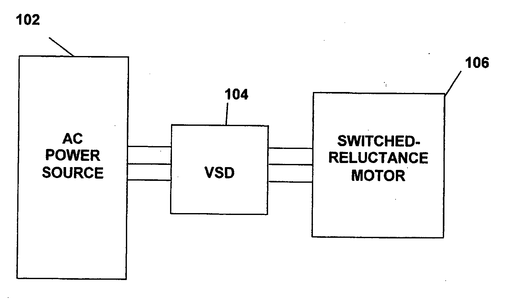
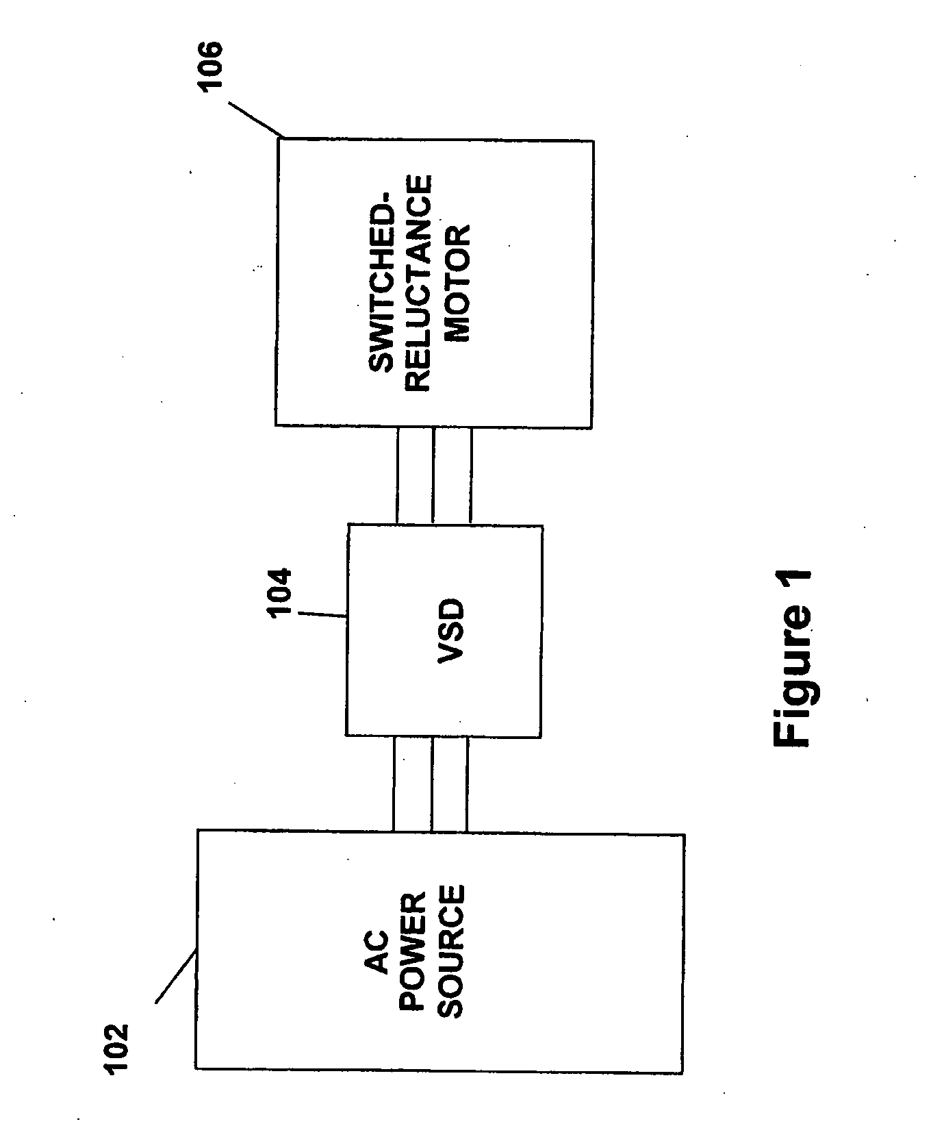
[0027]FIG. 1 illustrates generally a system configuration of the present invention. An AC power source 102 supplies a variable speed drive (VSD) 104, which powers a switched reluctance (SR) motor 106. In another embodiment of the present invention, the variable speed drive 104 can power more than one switched reluctance motor 106. The SR motor 106 is preferably used to drive a corresponding compressor of a refrigeration or chiller system (see generally, FIG. 3). The AC power source 102 provides single phase or multi-phase (e.g., three phase), fixed voltage, and fixed frequency AC power to the VSD 104 from an AC power grid or distribution system that is present at a site. The AC power source 102 preferably can supply an AC voltage or line voltage of 200 V, 230 V, 380 V, 460 V, or 600 V, at a line frequency of 50 Hz or 60 Hz, to the VSD 104 depending on the corresponding AC power grid.

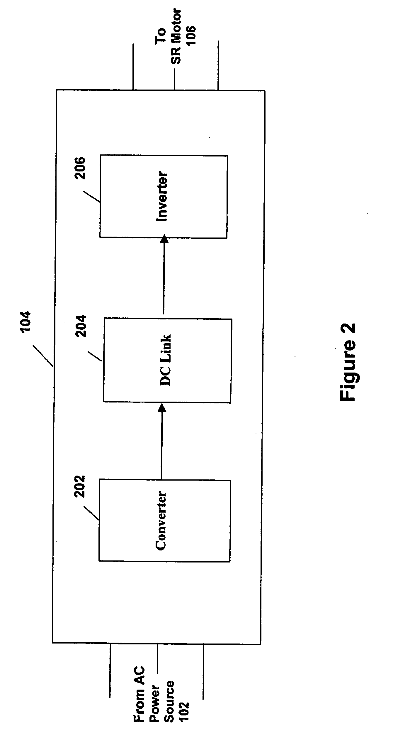
[0028] The VSD 104 receives AC power having a particular fixed line voltage and fixed line frequency...


PUM


Abstract

A chiller system includes a switched reluctance motor for powering the compressor of the chiller system. A variable speed drive with a boost converter provides a boosted voltage to the switched reluctance motor. The switched reluctance motor and the compressor may be disposed within the same hermetic enclosure and driven by a common drive shaft. Cooling for both the variable speed drive and the switched reluctance motor is provided from condenser water in the condenser water circuit, or from an intermediate liquid cooled by water from the condenser circuit to increase system efficiency. Windage losses are reduced by barriers introduced within the motor, and by maintaining a reduced pressure in the switched reluctance motor.

Description

BACKGROUND OF THE INVENTION [0001] The present invention relates generally to the method of applying a switched reluctance motor in a chiller system. More specifically, the present invention relates to a chiller system including a high-frequency switched reluctance variable speed drive for a switched reluctance motor that power a compressor of the chiller system. [0002] In the past, the induction motors for driving compressors in chiller systems were designed to operate from standard line (main) voltages and frequencies that were available from the power distribution system of the facility where the motor was being operated. The use of line voltages and frequencies typically required the compressors to use some inefficient mechanical means (such as inlet guide vanes for centrifugal compressors and a slide valve for screw compressors) for modulating capacity as a result of the motor being limited to one operating speed that was based on the input frequency to the motor. In addition, ...

Claims


Application Information

Patent Timeline
Patent Type & Authority Applications(United States)
IPC IPC(8): H02P1/46
CPCF25B31/006F25B49/025F25B2339/047F25B2600/021H02K7/14H02K9/12H02K9/19H02K2205/12H02P25/08Y02B30/741Y02B30/70H02K5/203
Inventor SMITH, STEPHEN HAROLDSCHNETZKA, HAROLD ROBERTJADRIC, IVAN
Owner JOHNSON CONTROLS TYCO IP HLDG LLP
Why Eureka
Try Eureka