An emc metal-plate antenna and a communication system using the same

a metal-plate antenna and communication system technology, applied in the structural form of the antenna, the structure of the antenna, the antenna earthing, etc., can solve the problems of reducing the usable space inside the wireless communication apparatus, reducing the performance of the antenna, and increasing the difficulty of design, so as to reduce the electromagnetic coupling effect, improve the receiving and transmitting quality of wireless signals, and avoid the effect of the antenna

Active Publication Date: 2007-05-17
IND TECH RES INST +1
View PDF14 Cites 37 Cited by
  • Summary
  • Abstract
  • Description
  • Claims
  • Application Information

AI Technical Summary

Benefits of technology

This patent describes two ways to reduce interference between a built-in antenna and other parts of a device that uses wireless signals. One way involves adding a layer of metal around the antenna called an EMC (electromagnetic compatibility) shielding metal wall. This helps prevent any unwanted signals from affecting the performance of the antenna. Additionally, both methods require no space between the antenna and the rest of the device's components, making them more efficient at sending and receiving signals.

Problems solved by technology

The technical problem addressed in this patent is how to create a wireless communication apparatus with a built-in antenna that has minimal impact from surrounding electronics while still maintaining optimal performance. Conventional methods require relatively large amounts of space within the apparatus and limit its overall size and flexibility. This patent proposes an innovative solution through the use of an EMC metal plate antenna that eliminates the necessity for isolated spacings between the antenna and other components, thereby minimizing interference and improving overall performance.

Method used


Image

  • An emc metal-plate antenna and a communication system using the same
  • An emc metal-plate antenna and a communication system using the same
  • An emc metal-plate antenna and a communication system using the same

Examples


first embodiment

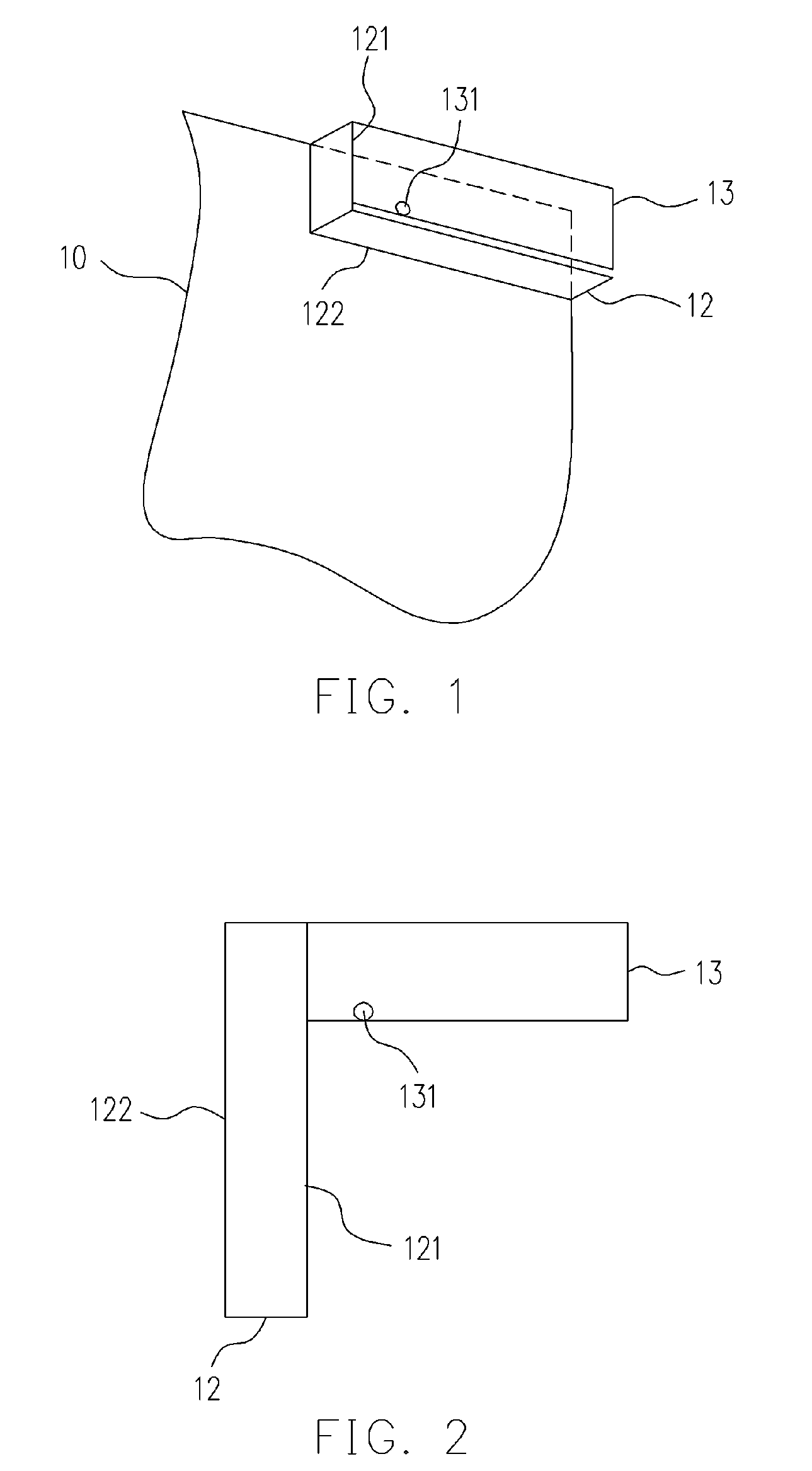
[0030] Referring to FIGS. 1 and 2 for showing an antenna according to the present invention. The antenna mainly includes a ground plane 10, a bent ground plate 12 and a radiating plate 13. The ground plane 10 is for signal ground of the entire antenna and the communication system using the antenna.

[0031] The bent ground plate 12 is perpendicular to the ground plane 10 and used as an electromagnetic shielding metal wall of the antenna for providing the antenna with a required shielding effect to effectively decrease the influence on the antenna from other electronic components (or signal sources) surrounding the antenna. The bent ground plate 12 is formed of a rectangle-like metal plate or a plate plated by metal or the equivalent. The bent ground plate 12 is formed by bending the rectangle-like metal plate or the plated plate at least once. In addition, the shape thereof after the bending is roughly of an L shape. The bent ground plate 12 has a first edge 121 and a second edge 122. ...

second embodiment

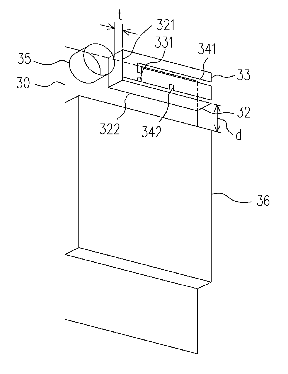
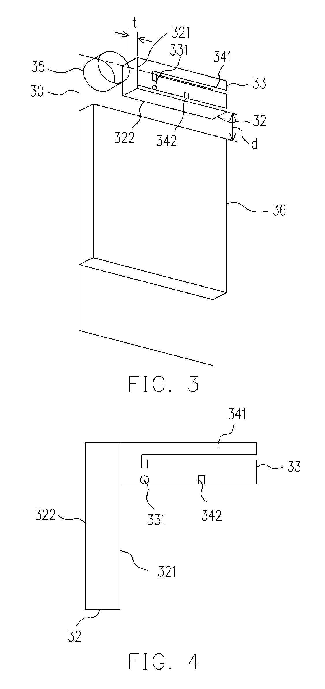
[0035] The antenna architecture of the second embodiment mainly includes a ground plane 30, a bent ground plate 32 and a radiating plate 33. The bent ground plate 32 is perpendicular to the ground plane 30 and is formed of a rectangle metal plate or a plate plated with metal or the equivalent. The bent ground plate 32 is formed by bending the metal plate or the plated plate at least once. In addition, the shape thereof after the bending is roughly of an L shape. The bent ground plate 32 has a first edge 321 and a second edge 322. The second edge 322 is electrically connected to the grounded plane 30. The radiating plate 33 is for generating operating resonant modes of the antenna. The radiating plate 33 has a signal feeding point 331 and two gaps 341 and 342, and is roughly parallel to the ground plane 30. The radiating plate 33 is electrically connected to the first edge 321 of the bent ground plate and encircled by the bent ground plate 32. The gap 341 makes two resonant paths in ...


PUM


Abstract

An EMC (electromagnetic compatible) antenna having a shielding metal wall to effectively reduce the possible coupling with nearby electronic elements is presented. The antenna includes: a ground plane, a bent ground plate, and a radiating plate. The bent ground plate is vertically connected to the ground plane and functions as an effective shielding metal wall to eliminate or greatly reduce the possible EM coupling between the antenna and nearby electronic elements. The radiating plate is used to generate the operating resonant mode of the antenna and is generally parallel to the ground plane. The radiating plate is also electrically connected to and encircled by the bent ground plane.

Description


Claims


Application Information

Patent Timeline
Owner IND TECH RES INST
Why Eureka
Try Eureka