Block redundancy implementation in heirarchical ram's

a technology of block redundancy and block redundancy, applied in the field of programable devices, can solve the problems of high-performance memory architectures that place a severe strain on the power and area budgets of the associated systems, require complex fabrication and manufacturing processes, and require high-performance components such as memory cells. to achieve the effect of not incurring excessive access time or area overhead penalties

Inactive Publication Date: 2007-05-17
AVAGO TECH INT SALES PTE LTD
View PDF20 Cites 10 Cited by
  • Summary
  • Abstract
  • Description
  • Claims
  • Application Information

AI Technical Summary

Benefits of technology

[0010] The present invention relates to a system and method for providing redundancy in a hierarchically partitioned memory, by replacing small blocks in such memory for example. One embodiment provides such redundancy (i.e., replaces such small blocks) by either shifting predecoded lines or using a modified shifting predecoder circuit in the local predecoder block. Such block redundancy scheme, in accordance with the present invention, does not incur excessive access time or area overhead penalties, making it attractive where the memory subblock size is small.

Problems solved by technology

High-performance memory architectures place a severe strain on the power and area budgets of the associated systems, particularly where such components are embedded within a VLSI system, such as a digital signal processing system for example.
Highly integrated, high performance components, such as memory cells for example, require complex fabrication and manufacturing processes.
These processes may experience unavoidable parameter variations which may impose physical defects upon the units being produced, or may exploit design vulnerabilities to the extent of rendering the affected units unusable, or substandard.
In memory architectures, redundancy may be important, as a fabrication flaw or operational failure in the memory architecture may result in the failure of that system.
Lacking redundancy and process invariant features, the actual manufacturing yield for particular memory architecture may be unacceptably low.
Low-yield memory architectures are particularly unacceptable when embedded within more complex systems, which inherently have more fabrication and manufacturing vulnerabilities.

Method used


Image

  • Block redundancy implementation in heirarchical ram's
  • Block redundancy implementation in heirarchical ram's
  • Block redundancy implementation in heirarchical ram's

Examples


Embodiment Construction

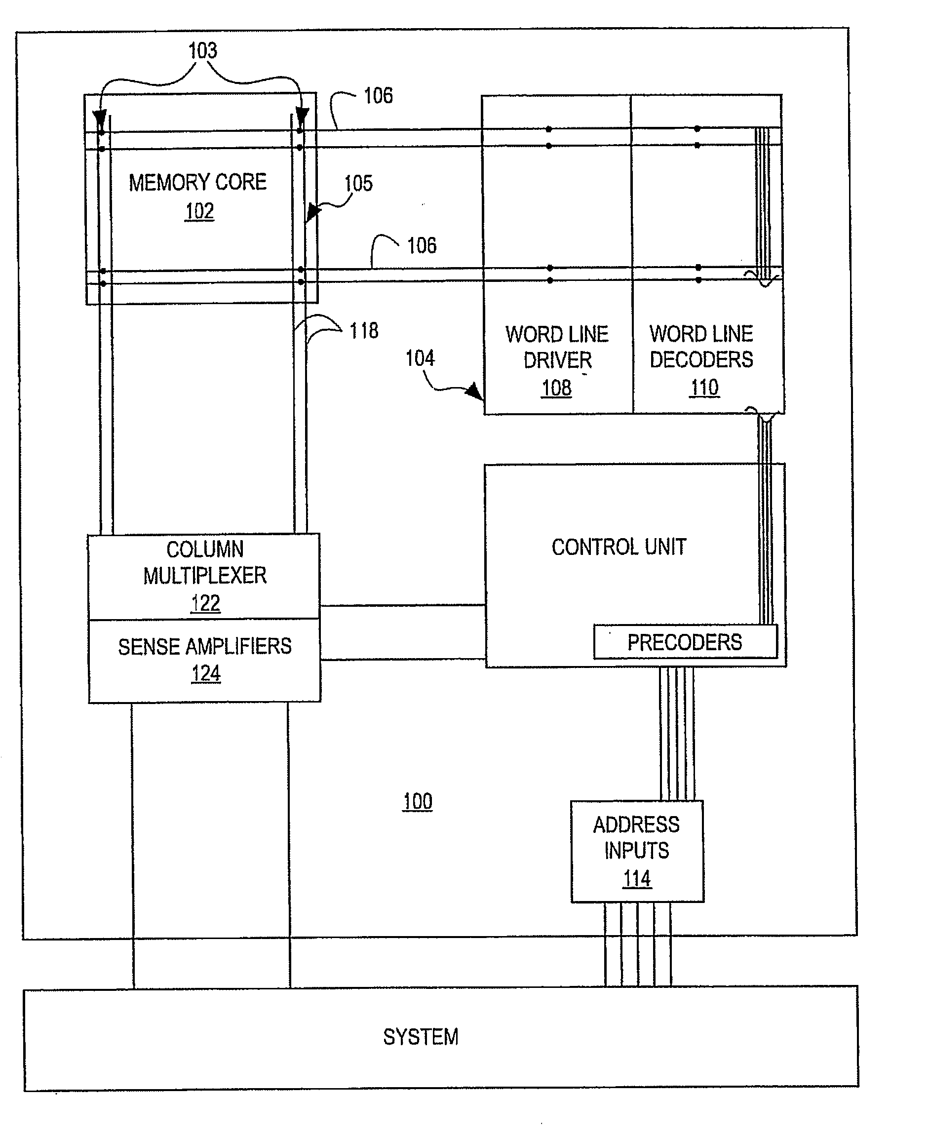
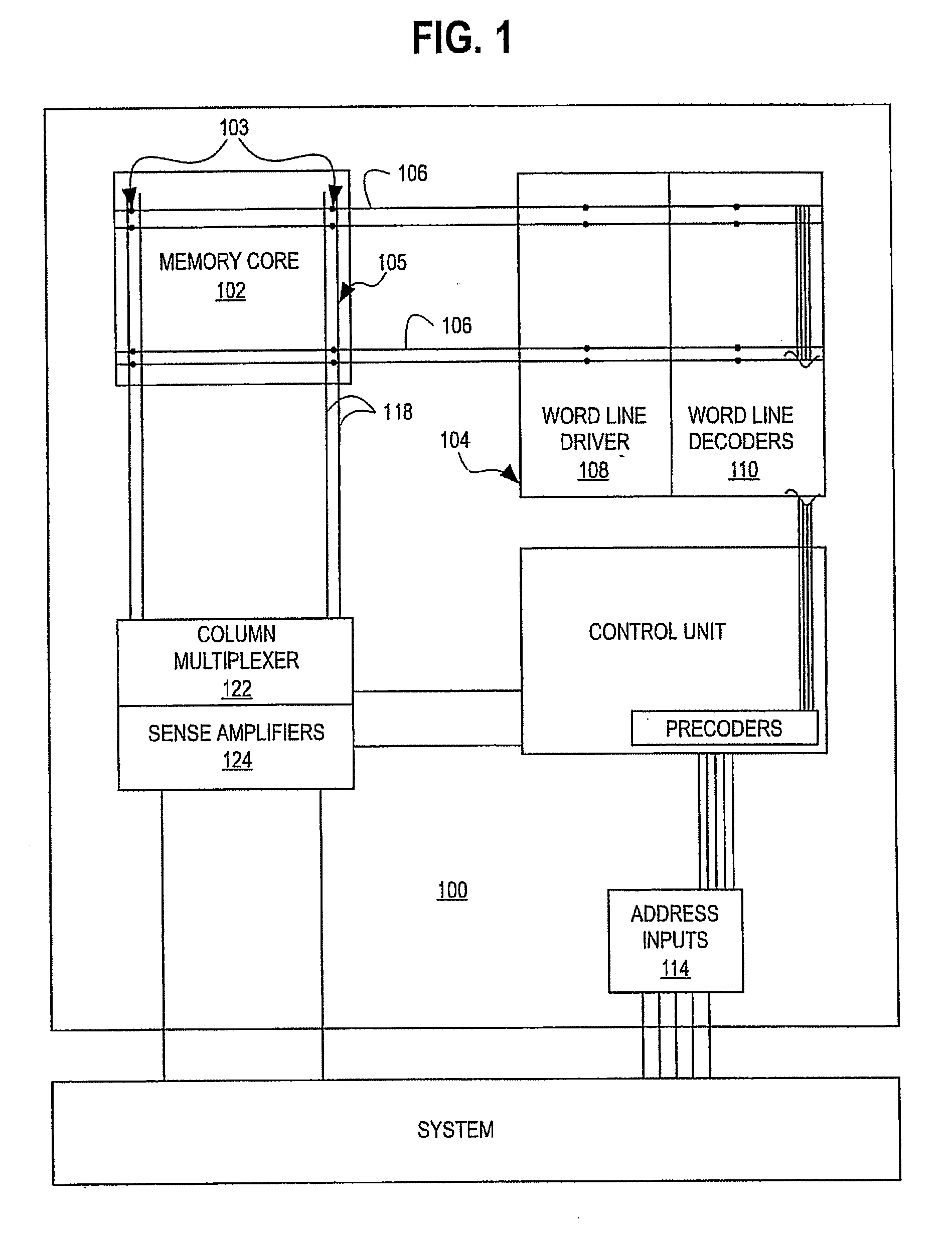
[0057] As will be understood by one skilled in the art, most VLSI systems, including communications systems and DSP devices, contain VLSI memory subsystems. Modern applications of VLSI memory subsystems almost invariably demand high efficiency, high performance implementations that magnify the design tradeoffs between layout efficiency, speed, power consumption, scalability, design tolerances, and the like. The present invention ameliorates these tradeoffs using a novel synchronous, self-timed hierarchical architecture. The memory module of the present invention also may employ one or more novel components, which further add to the memory module's efficiency and robustness.

[0058] It should be appreciated that it is useful to describe the various aspects and embodiments of the invention herein in the context of an SRAM memory structure, using CMOS SRAM memory cells. However, it should be further appreciated by those skilled in the art the present invention is not limited to CMOS-bas...


PUM


Abstract

The present invention relates to a system and method for providing redundancy in a hierarchically memory, by replacing small blocks in such memory. The present invention provides such redundancy (i.e., replaces such small blocks) by either shifting predecoded lines or using a modified shifting predecoder circuit in the local predecoder block. In one embodiment, the hierarchal memory structure includes at least one active predecoder adapted to be shifted out of use; and at least one redundant predecoder adapted to be shifted in to use.

Description

CROSS REFERENCE TO RELATED APPLICATIONS [0001] This application is a continuation of “Block Redundancy Implementation in Heirarchical RAM'S”, U.S. application Ser. No. 10 / 729,405 filed Dec. 5, 2003, which issued as U.S. Pat. No. ______, on ______, which was a continuation of “Block Redundancy Implementation in Heirarchical RAMS”, U.S. application Ser. No. 10 / 176,843 filed Jun. 21, 2003, which issued as U.S. Pat. No. 6,714,467, on Mar. 30, 2004, which was a continuation-in-part of, and claims benefit of and priority from, application Ser. No. 10 / 100,757 filed Mar. 19, 2002, titled “Synchronous Controlled, Self-Timed Local SRAM Block”, which issued as U.S. Pat. No. 6,646,954 on Nov. 11, 2003 and U.S. application Ser. No. 09 / 775,701 filed Feb. 2, 2001 which issued as U.S. Pat. No. 6,411,557. The complete subject matter of each of the foregoing applications are incorporated herein by reference in their entirety.FEDERALLY SPONSORED RESEARCH OR DEVELOPMENT [0002] [Not Applicable]BACKGROUN...

Claims


Application Information

Patent Timeline
Patent Type & Authority Applications(United States)
IPC IPC(8): G11C29/00G06F13/40G11C7/06G11C7/18G11C11/419
CPCG06F13/4086G11C7/06G11C7/18G11C11/41Y02B60/1235G11C29/808G11C29/81G11C29/848Y02B60/1228G11C11/419Y02D10/00
Inventor TERZIOGLU, ESINWINOGRAD, GIL I.AFGHAHI, CYRUS
Owner AVAGO TECH INT SALES PTE LTD
Why Eureka
Try Eureka