Measuring system and method for optical network

a technology of optical network and measuring system, applied in the field of measuring system and method, can solve the problems of increasing the entire detection cost, the signal generator b>13/b> is an expensive apparatus, etc., and achieves the effect of reducing the cost of the entire measuring system, and simulating the tdma transmission

Inactive Publication Date: 2007-05-17
DELTA ELECTRONICS INC
View PDF7 Cites 0 Cited by
  • Summary
  • Abstract
  • Description
  • Claims
  • Application Information

AI Technical Summary

Benefits of technology

[0012] As mentioned above, the measuring system and method for an optical network uses a signal dividing device to generate a control signal according to the data signal. The control signal is then delivered to one of the ONU's at different time slots. It controls one of the ONU's to deliver the data signal to the OLT, thereby simulating the TDMA transmissions. The data signal received by the OLT is measured in order to determine the error rate and sensitivity of the optical network. In comparison with the prior art, the disclosed measured system and method for an optical network only needs one signal generator to measure the optical network, thus reducing the cost of the entire measuring system.

Problems solved by technology

However, the signal generator 13 is an expensive apparatus.
This method thus increases the entire detection cost.

Method used


Image

  • Measuring system and method for optical network
  • Measuring system and method for optical network
  • Measuring system and method for optical network

Examples


Embodiment Construction

[0017] The present invention will be apparent from the following detailed description, which proceeds with reference to the accompanying drawings, wherein the same references relate to the same elements.

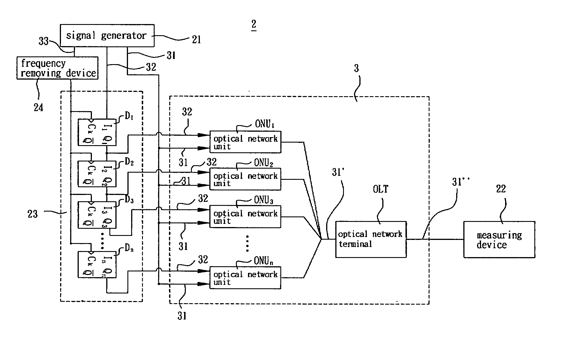
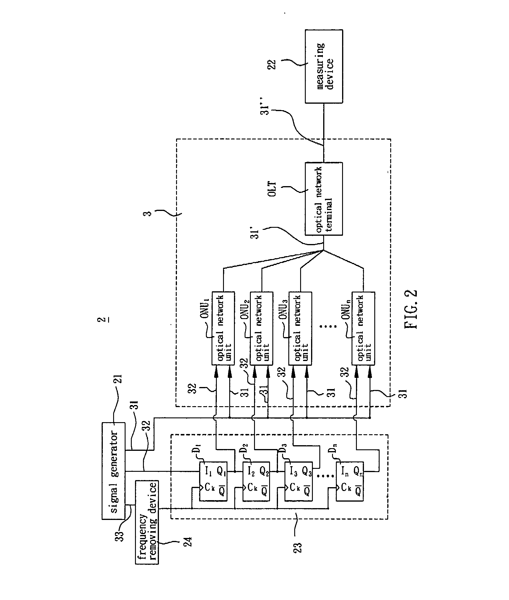
[0018] A preferred embodiment of a measuring system for an optical network is schematically shown in FIG. 2.

[0019] The optical network 3 is a passive optical network (PON) and has several optical network units (ONU) ONU1.ONUn and an optical network terminal (OLT). The ONU's ONU1.ONUn are connected to the OLT via several optical fibers of different lengths, thereby forming the optical network 3.

[0020] The measuring system 2 in this embodiment can be used to measure the sensitivity and error rate in the above-mentioned optical network 3. The measuring system 2 includes a signal generator 21, a measuring device 22, and a signal dividing device 23. The signal generator 21 is a pulse pattern generator (PPG) for generating a data signal 31, a control signal 32, and a pulse signal 33. Th...


PUM


Abstract

A measuring system for an optical network, which has a plurality of optical network units and an optical line terminal, includes a signal generator, a signal dividing device and a measuring device. The signal generator produces a data signal and a control signal, which is then delivered to the optical network units. The signal dividing device delivers the control signal to one of the optical network units at a first time, and then delivers the control signal to another optical network unit at the second time. The optical network unit delivers the data signal to the optical line terminal after receiving the control signal. The measuring device measures the data signal received by the optical line terminal.

Description

CROSS REFERENCE TO RELATED APPLICATIONS [0001] This Non-provisional application claims priority under 35 U.S.C. 119(a) on Patent Application No(s). 094139635 filed in Taiwan, Republic of China on Nov. 11, 2005, the entire contents of which are hereby incorporated by reference. BACKGROUND OF THE INVENTION [0002] 1. Field of Invention [0003] The invention relates to a measuring system and method. In particular, the invention relates to a measuring system and method for an optical network. [0004] 2. Related Art [0005] With the rapid growth of the Internet, users have higher demands for transmission bandwidths. Therefore, a broadband optical network becomes one of the best solutions. [0006]FIG. 1 shows a conventional optical network. Generally speaking, the optical network 1 is a passive optical network (PON) with a point-to-many-point (P2MP) structure. The optical network 1 has several optical network units (ONU) 11 and an optical line terminal (OLT) 12. The optical network 1 can adopt...

Claims


Application Information

Patent Timeline
Patent Type & Authority Applications(United States)
IPC IPC(8): H04J14/00G01M11/00H04B10/07H04B10/27H04B10/272H04B10/524
CPCH04B10/079H04L1/242
Inventor YANG, HENG-YI
Owner DELTA ELECTRONICS INC
Why Eureka
Try Eureka