Cable connector

a technology of cable connectors and connectors, applied in the direction of printed circuit parts, coupling device connections, printed circuit manufacturing, etc., can solve problems such as adversely affecting signals, and achieve the effect of improving the transmission property of cable connectors

Inactive Publication Date: 2007-05-17
FUJITSU COMPONENENT LTD
View PDF5 Cites 56 Cited by
  • Summary
  • Abstract
  • Description
  • Claims
  • Application Information

AI Technical Summary

Benefits of technology

[0015] Another and more specific object of the present invention is to provide a cable connector configured to include a relay wiring substrate in which a transmission property at a part of the relay wiring substrate is improved.
[0017] According to at least one embodiment of the present invention, the impedance of a section where a signal contact is connected to a contact connecting pad is matched to a predetermined value by a ground pattern for matching impedance so that a transmission property of a cable connector is improved.

Problems solved by technology

Especially, in the case where the signal is transmitted at a high speed, a change of the impedance at even one part may adversely affect the signal.

Method used


Image

  • Cable connector
  • Cable connector
  • Cable connector

Examples


first embodiment

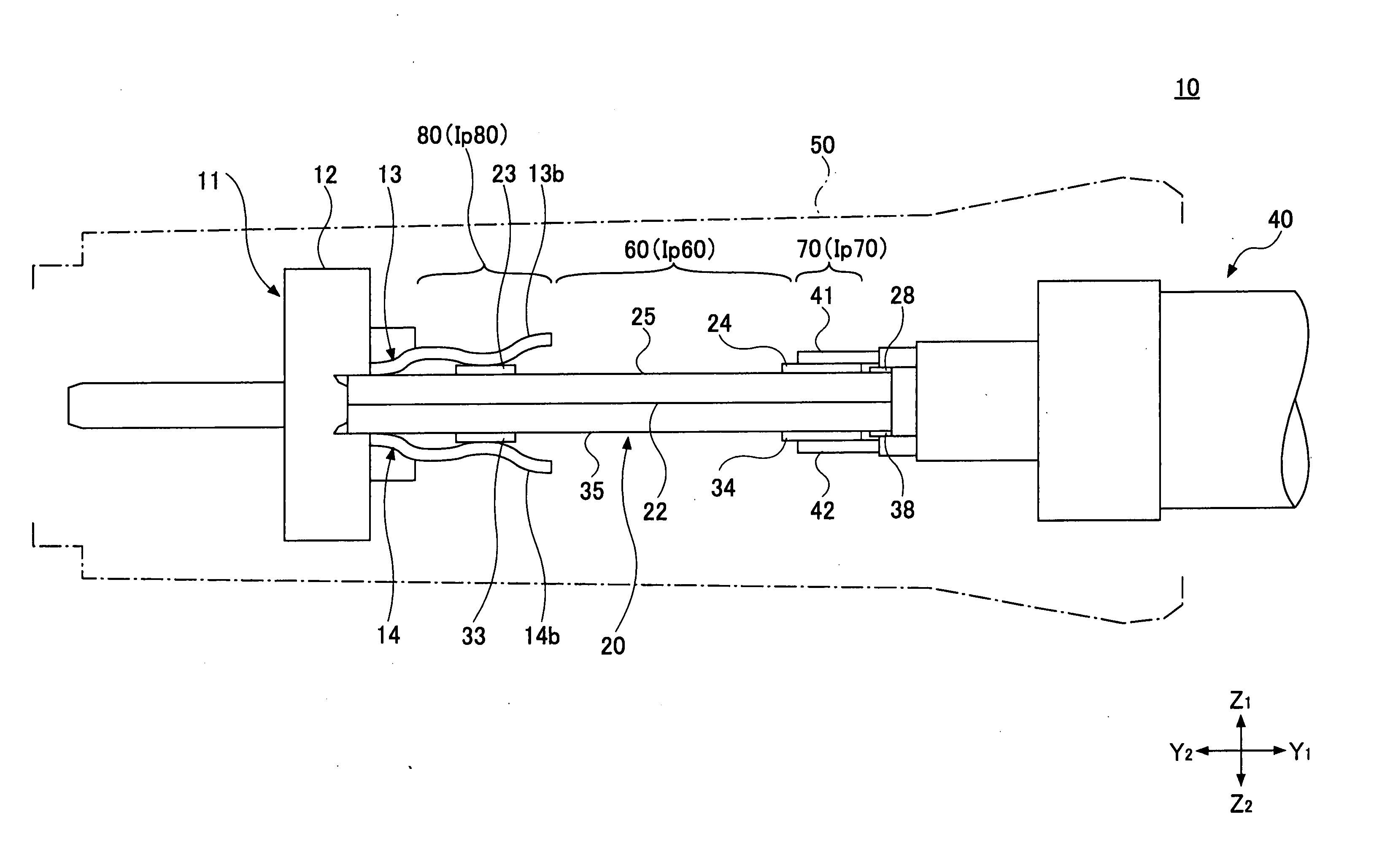
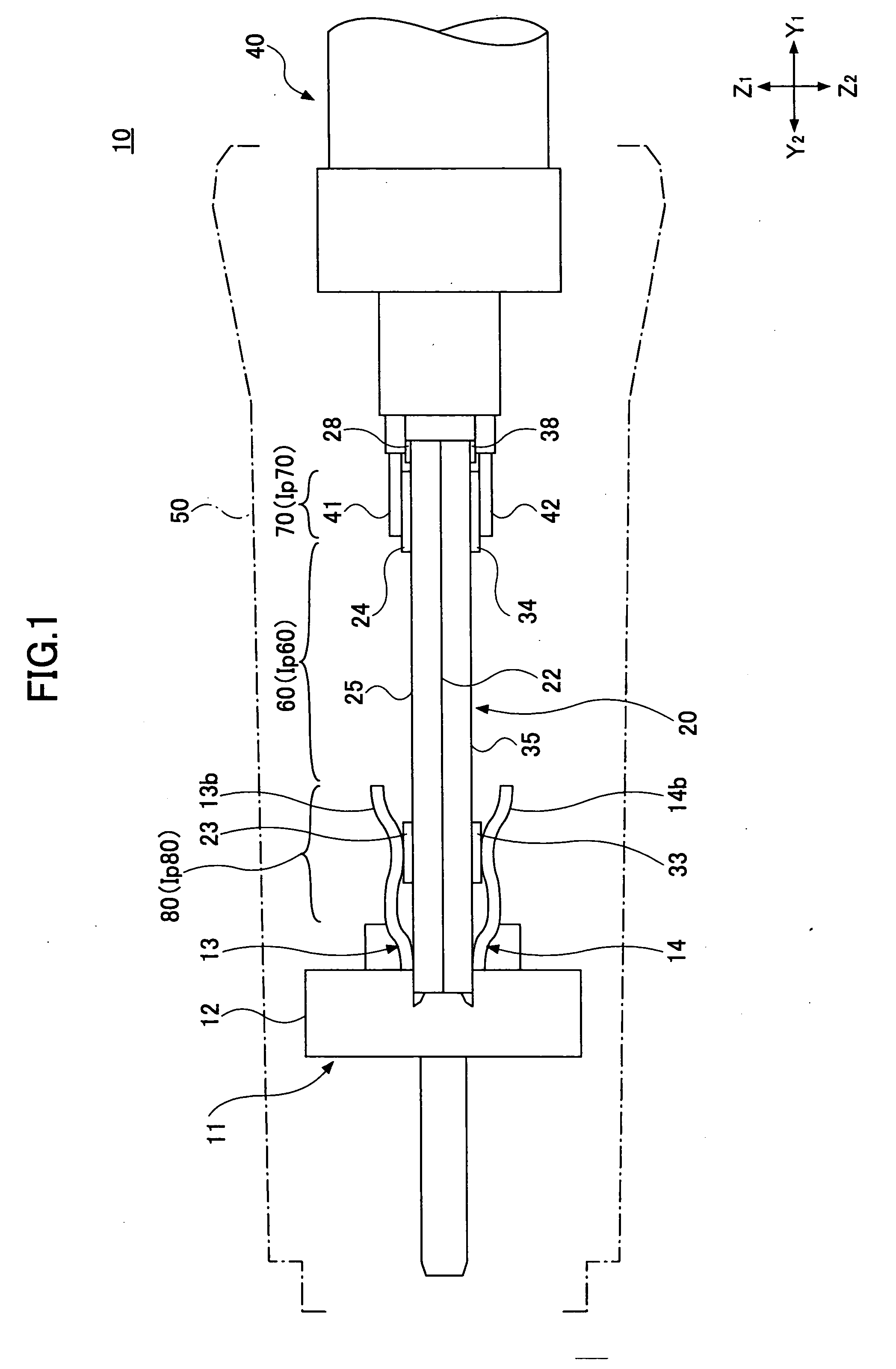
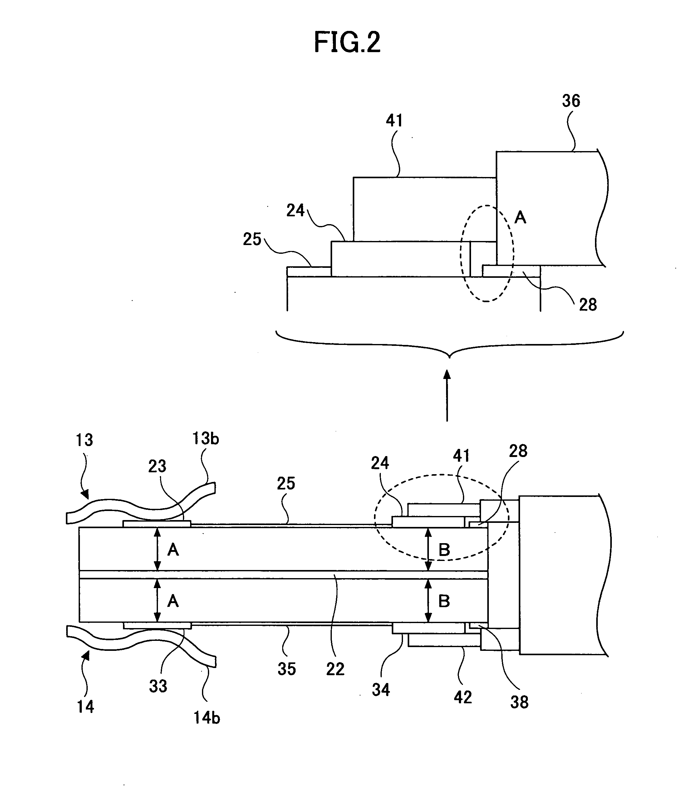
[0039]FIG. 4 is a view schematically showing a cable connector 100 for a balanced transmission according to a first embodiment of the present invention. FIG. 5 is a schematic diagram illustrating a relay wiring substrate 120 in FIG. 4 and a part where the relay wiring substrate 120, the cable 40 for the balanced transmission, and the contact assembly 11 are connected together. FIGS. 6A and 6B are views illustrating the cable connector 100 for the balanced transmission where a shield housing 50 is removed. FIG. 7 is a view illustrating a contact assembly. FIGS. 8A and 8B are perspective views illustrating the relay wiring substrate. FIG. 9 is a schematic diagram illustrating the relay wiring substrate. FIG. 10 is a view illustrating the relay wiring substrate where a pattern thereof is taken out. FIGS. 11A and 11B are views illustrating a cable for the balanced transmission. In the drawings, the lines X1-X2, Y1-Y2, and Z1-Z2 show a width direction, a length direction, and a height di...

first modified example

[0061]FIG. 12 is a view of a first modified example of a relay wiring substrate 120A. The relay wiring substrate 120A comprises two ground layers 122-1 and 122-2. The ground layers 122-1 and 122-2 are formed on the upper and under surfaces of a base member 150, respectively.

second modified example

[0062]FIG. 13 is a view of a second modified example of a relay wiring substrate 120B. The relay wiring substrate 120B differs from the relay wiring substrate 120 shown in FIG. 9 in including a first wiring connecting pad 124B and a second wiring connecting pad 134B.

[0063] The first wiring connecting pad 124B comprises, as shown by an enlarged view of FIG. 13, preliminary soldering portions 161 and 162 at opposite ends in the width direction of a ground pattern 160 so that a groove portion 163 is formed by the preliminary soldering portions 161 and 162. The wiring 41 is appropriately arranged by engaging the groove portion 163 and being soldered onto a center of the ground pattern 160. The wiring 41 may be crushed so that a cross-section thereof is ovalized as shown in FIG. 13.

[0064] As shown in FIG. 14A, a heat-resistant tape 164 is attached onto the center of the ground pattern 160. Cream solder 165 is applied to the ground pattern 160 as shown in FIG. 14B, and then heated so th...


PUM


Abstract

A cable connector includes a contact assembly including an electrical insulating block part which is configured to incorporate plural signal contacts; and a relay wiring substrate mounted to a back of the contact assembly. The relay wiring substrate includes, on a surface, a contact connecting pad electrically connected to one of the signal contacts, a wiring connecting pad, and a wiring pattern connecting the contact connecting pad and the wiring connecting pad. The relay wiring substrate further includes a ground layer inside the relay wiring substrate. The cable connector further includes a cable connected to the relay wiring substrate by electrically connecting an end of a wiring with the wiring connecting pad. The relay wiring substrate further includes a ground pattern for matching impedance inside the relay wiring substrate.

Description

BACKGROUND OF THE INVENTION [0001] 1. Field of the Invention [0002] The present invention generally relates to a cable connector, and more particularly, a cable connector for a balanced transmission having a relay wiring substrate in which a contact assembly is joined to the relay wiring substrate, and an end of a cable is connected to an end of the relay wiring substrate. [0003] 2. Description of the Related Art [0004] As for methods of data transmission, for example, a normal transmission method is provided in which one wiring is used for each data signal. Further, a method of a balanced transmission is provided in which a pair of wirings are used for each data signal. Through the pair of wirings, a plus signal and a minus signal are simultaneously transmitted, which minus signal has the same size as the plus signal and a polarity reverse to the plus signal. The method of the balanced transmission has an advantage in that the balanced transmission is less susceptible to noise than...

Claims


Application Information

Patent Timeline
Patent Type & Authority Applications(United States)
IPC IPC(8): H01R9/05
CPCH01R9/0515H01R13/6658H01R24/44H01R2103/00H05K3/3405H05K3/3484H05K2201/09745H05K2201/099H05K2201/09909H05K2201/10287H05K2201/10356H05K2203/0191H05K2203/0195H05K2203/043H05K2203/0545H05K3/3485
Inventor KONDOU, TAKAHIROSATO, KIYOSHIKOBAYASHI, MITSURUMORIYAMA, SATOSHI
Owner FUJITSU COMPONENENT LTD
Why Eureka
Try Eureka