
Needle shield to septum interconnect

a technology of septum and needle shield, which is applied in the direction of intravenous devices, catheters, injection needles, etc., can solve the problems of increasing friction, elongation of the septum, and difficult process in practi

Active Publication Date: 2007-05-17
BECTON DICKINSON & CO
View PDF50 Cites 64 Cited by
  • Summary
  • Abstract
  • Description
  • Claims
  • Application Information

AI Technical Summary

Benefits of technology

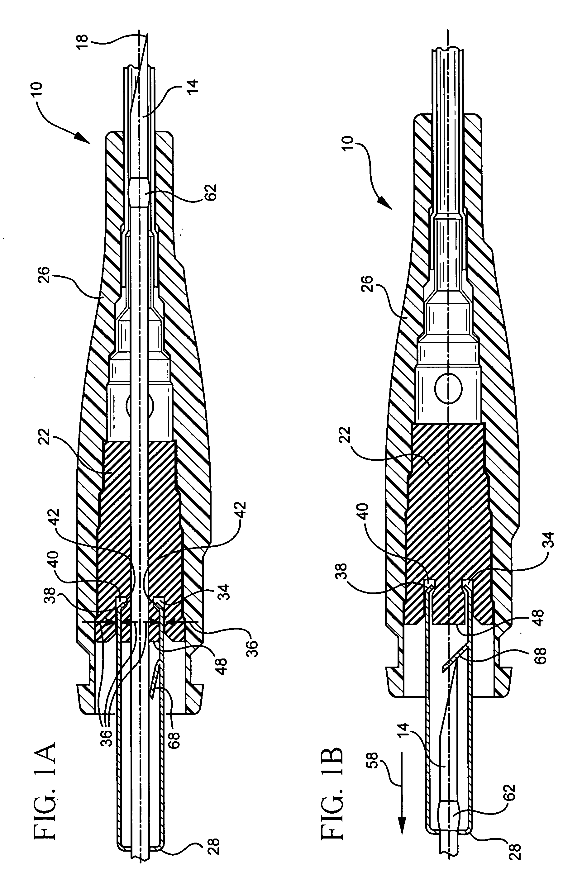
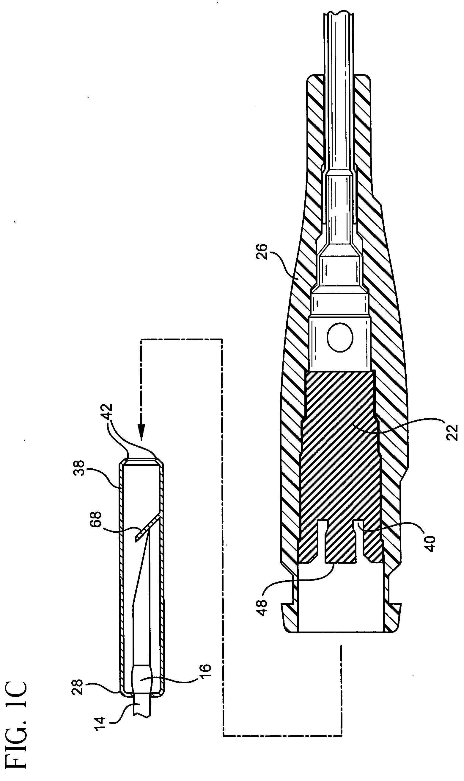
[0013] In order that the manner in which the above-recited and other features and advantages of the invention are obtained will be readily understood, a more particular description of the invention briefly described above will be rendered by reference to specific embodiments thereof which are illustrated in the appended drawings. Understanding that these drawings depict only typical embodiments of the invention and are not therefore to be considered to be limiting of its scope, the invention will be described and explained with additional specificity and detail through the use of the accompanying drawings in which:

Problems solved by technology

This process has been somewhat difficult in practice since many placement sites simply do not allow easy occlusion of the target vessel.
Additionally, even when such occlusion is achieved, it may be imperfect, thus resulting in blood leaking from the catheter, endangering the medical personnel employing it.
This elongation of the septa increases the amount of friction placed on the needle, the amount of effort needed to remove it, and the potential of damaging the product.

Method used


Image

  • Needle shield to septum interconnect
  • Needle shield to septum interconnect
  • Needle shield to septum interconnect

Examples


Embodiment Construction

[0030] The presently preferred embodiments of the present invention will be best understood by reference to the drawings, wherein like parts are designated by like numerals throughout. It will be readily understood that the components of the present invention, as generally described and illustrated in the figures herein, could be arranged and designed in a wide variety of different configurations. Thus, the following more detailed description of the embodiments of the catheter device of the present invention, as represented in FIGS. 1A through 7D, is not intended to limit the scope of the invention, as claimed, but is merely representative of presently preferred embodiments of the invention.

[0031] Referring now to FIG. 1A, a perspective view of a catheter device 10 according to the present embodiments are illustrated. The catheter device 10 may include a needle 14 having a sharp or relatively sharp tip 18. As is known by those of skill in the art, the needle 14 and the needle tip 1...


PUM


Abstract

The present invention is a catheter device. The catheter device will include a septum that is housed within a housing. The septum is designed such that it will seal the housing. The catheter device also includes a needle shield. The needle shield is configured to retain a needle if the needle is withdrawn from the housing. The catheter device is further configured such that the septum includes a receiving portion that is designed to engage a portion of the needle shield. However, if the needle is withdrawn from the housing, the needle shield will disengage from the septum so that the needle shield may be separated from the septum.

Description

BACKGROUND OF THE INVENTION [0001] The present invention relates to catheter and introducer needle assemblies. In medicine, such catheter and introducer needle assemblies are used to place a catheter properly into the vascular system of a patient. Once in place, catheters such as intravenous (or “IV”) catheters may be used to infuse fluids including normal saline, medicinal compounds, and / or nutritional compositions (including total parenteral nutrition, or “TPN”) into a patient in need of such treatment. Catheters additionally enable the removal of fluids from the circulatory system and monitoring of conditions within the vascular system of the patient. [0002] One type of commonly-used catheter is a peripheral intravenous catheter. These short, indwelling intravenous catheters are often used to provide an entry route for medications, fluid for hydration, and in some cases, for parenteral feeding, into a patient. Such catheters are generally short in length, ranging from about one-h...

Claims


Application Information

Patent Timeline
Patent Type & Authority Applications(United States)
IPC IPC(8): A61M5/178
CPCA61M5/3273A61M25/0606A61M25/0618A61M2005/325
Inventor BRIMHALL, GREG L.
Owner BECTON DICKINSON & CO
Learn More