Floor scrubber

Active Publication Date: 2007-05-24
FNA GROUP INC
View PDF38 Cites 38 Cited by
  • Summary
  • Abstract
  • Description
  • Claims
  • Application Information

AI Technical Summary

Benefits of technology

[0008] Still a further object is to provide a floor scrubber of the above type which is effective for permittin

Problems solved by technology

Conventional scrubbers suffer from a number of drawbac

Method used


Image

  • Floor scrubber
  • Floor scrubber
  • Floor scrubber

Examples


Embodiment Construction

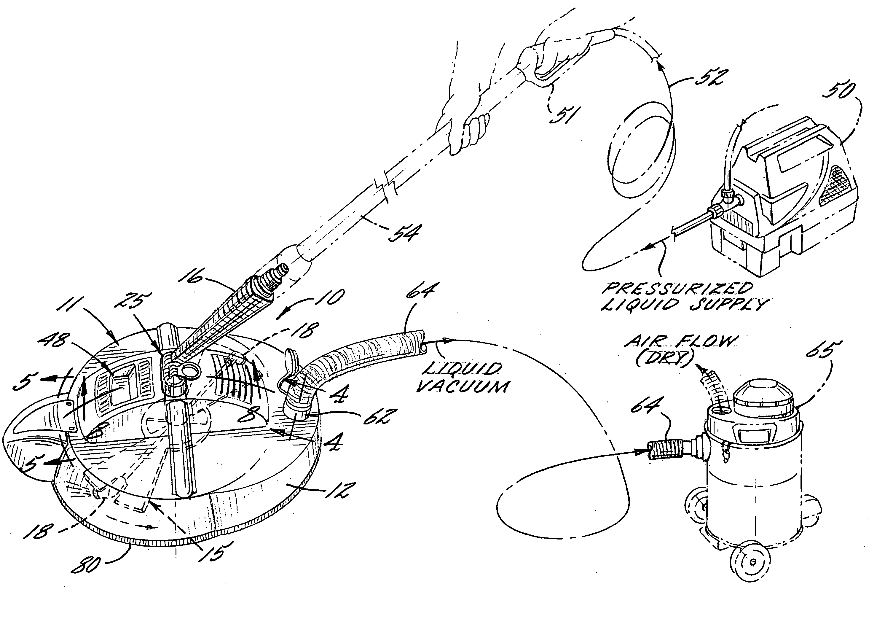
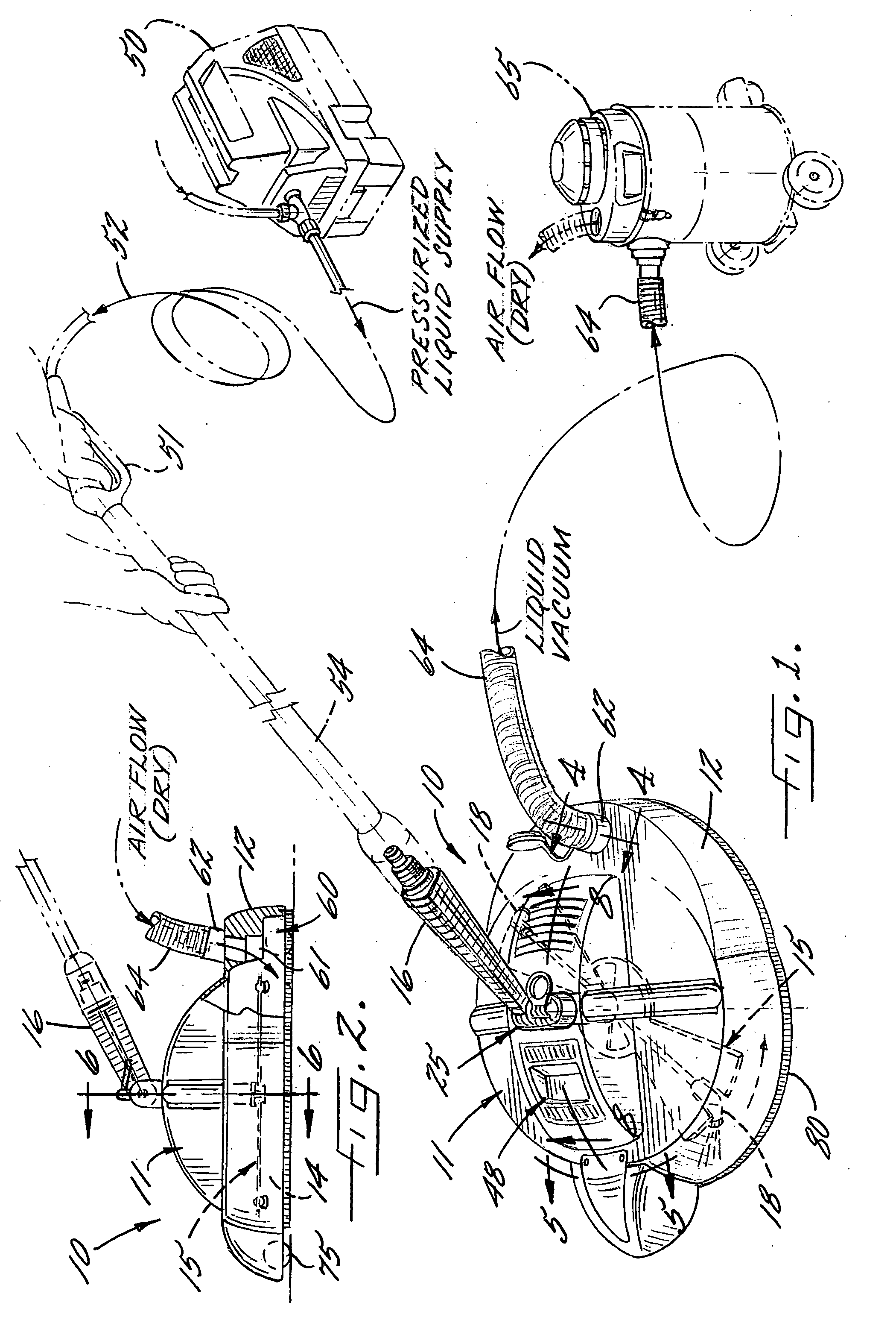
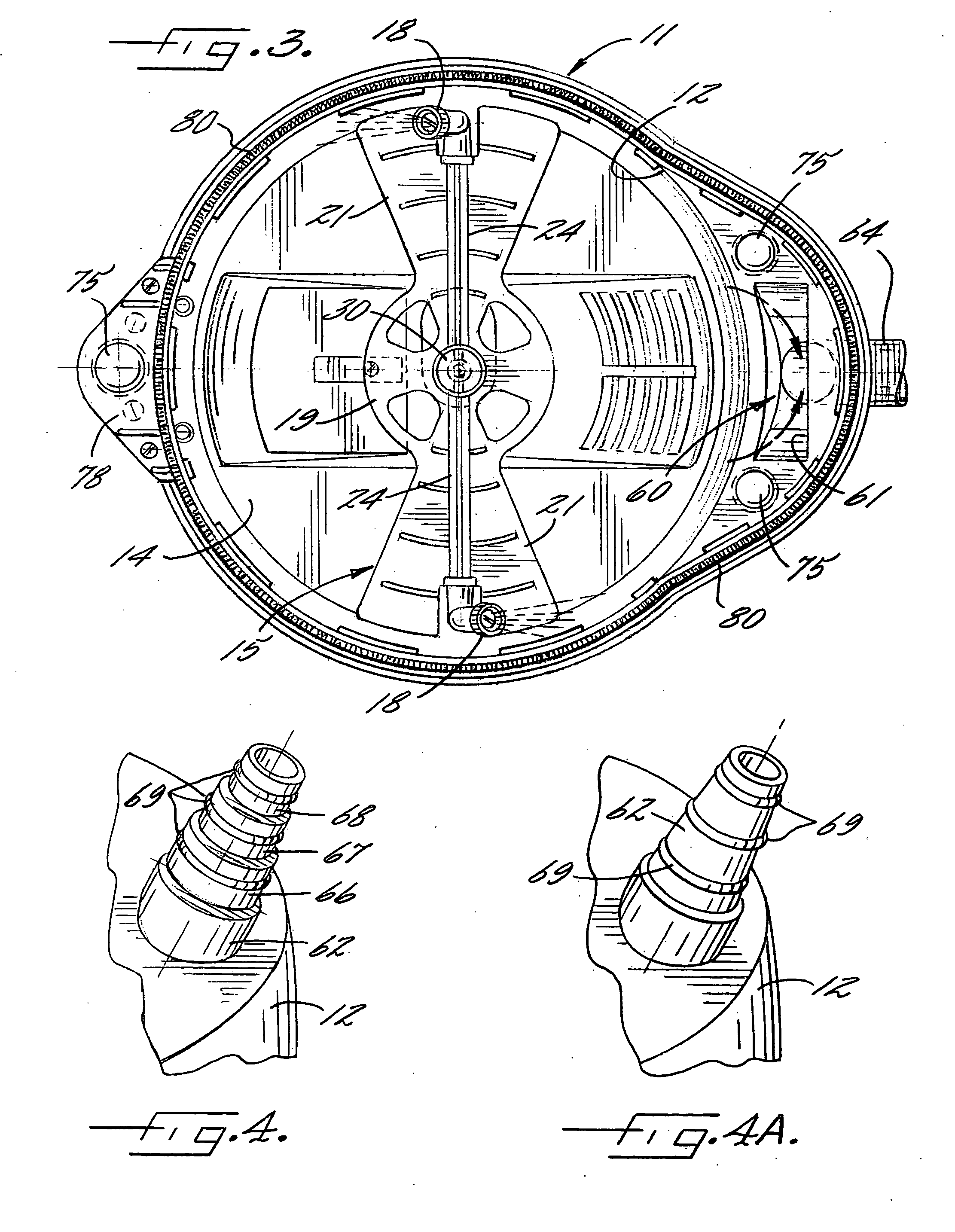
[0028] Referring now more particularly to the drawings, there is shown an illustrative floor scrubber 10 in accordance with the invention which comprises a spray or cleaning head 11 having a housing 12, preferably molded of rigid plastic material, that defines a downwardly opening spray or cleaning chamber 14, a spray nozzle assembly 15 disposed within the cleaning chamber 14, and a pivotably adjustable adaptor 16 for connection to a pressurized liquid supply for directing a cleaning fluid, typically water, to the spray nozzle assembly 15 for pressurized direction onto the floor surface during a cleaning operation. The spray nozzle assembly 15 in this case includes a pair of spray nozzles 18 disposed at diametrically opposed ends of a rotary arm 19. The rotary arm 19 is in the form of a pair of radial wings 21 extending from diametrically opposed sides of a central hub 20 parallel to the floor surface to be cleaned for preventing splash back of the sprayed liquid into the spray head...


PUM


Abstract

A floor scrubber for cleaning floor surfaces that includes a cleaning head which defines a downwardly opening cleaning zone having a plurality of spray nozzles connected to a power washer pump for directing pressurized liquid flow streams onto the floor surface during a cleaning operation. The cleaning head further defines a separate downwardly opening vacuum zone connected to a wet/dry vacuum device operable for creating a vacuum pressure within the vacuum zone for removing liquid that has been directed onto the floor surface. The wet/dry vacuum device preferably further is operable for selectively directing a positive air flow into the vacuum zone to facilitate drying of the floor surface after cleaning and vacuum removal of the liquid.

Description

FIELD OF THE INVENTION [0001] The present invention relates generally to floor scrubbing devices, and more particularly, to scrubbing devices of the type that direct pressurized liquid flow streams onto the floor during a cleaning operation. BACKGROUND OF THE INVENTION [0002] Floor scrubbers are known of the type which have a cleaning head or housing that is moveable along the floor and which have a plurality of downwardly directed liquid spray nozzles that communicate with a pressurized liquid supply, such as through a liquid flow passageway in a handle of the scrubber. Conventional scrubbers suffer from a number of drawbacks that detract from their widespread efficient usage. Most significantly, while such floor scrubbers can be effective in cleaning floor surfaces, considerable water is directed onto the floor which must later be mopped up or otherwise disposed of to complete the cleaning task. For that purpose, the user of the floor scrubber, often a homeowner, must employ addit...

Claims


Application Information

Patent Timeline
IPC IPC(8): A47L11/30
CPCA47L11/03A47L11/4044A47L11/4088B08B3/024B08B3/026B08B2203/0229
Inventor ALEXANDER, GUS
Owner FNA GROUP INC
Why Eureka
Try Eureka