
Rotary electric shaver

a rotary electric shaver and electric shaver technology, applied in metal working devices and other directions, can solve the problems of difficult control of sound quality, affecting the quality of shaving comfort,

Inactive Publication Date: 2007-05-24
IZUMI PROD CO
View PDF6 Cites 8 Cited by
  • Summary
  • Abstract
  • Description
  • Claims
  • Application Information

AI Technical Summary

Benefits of technology

[0013] Accordingly, the object of the present invention, devised in view of such circumstances as described above, is to provide an electric shaver of a rotary type in which it is made to be able to control the sound quality without causing the cutter blades of the inner cutter to vibrate.
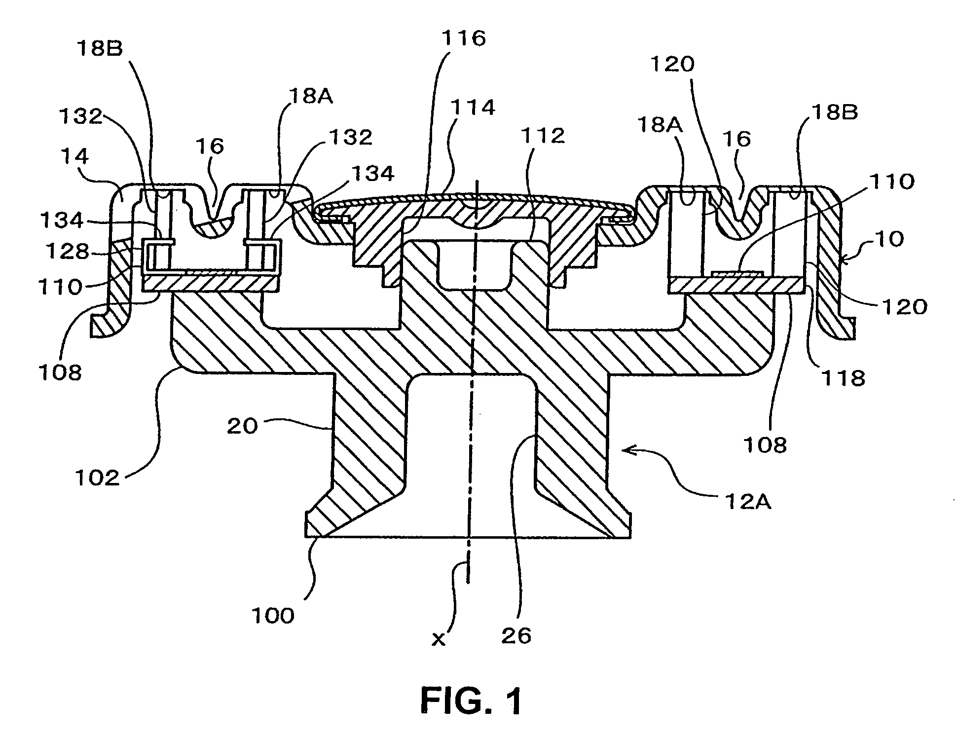
[0016] As seen from the above, in the shaver of the present invention, a vibration element(s) is provided on the inner cutter(s), and this vibration element(s) has a smaller spring constant in the direction in which the cutter blade(s) travels and in the opposite direction therefrom than that of the cutter blade(s) of the inner cutter(s), and this vibration element(s) is made so as to vibrate while sliding in the ring-shaped track(s) of the outer cutter. Accordingly, by suitably setting the vibration characteristics of the vibration element, the sound quality is enhanced. It is thus also possible to use cutter blades that have sufficiently high rigidity so as to be able to cut the hair efficiently and provide good cutting quality.
[0017] The vibration element(s) is formed of a metal sheet, thinner than the cutter blade(s), so that the tip end of the vibration element(s) slides against the ring-shaped track(s); and a straight line joining the flexible bending point of the vibration element and the cutting edge formed on the front edge of the vibration element is set to be substantially parallel to the rotational axis of the inner cutter. In this structure, when the vibration element(s) vibrates forwards and backwards along the ring-shaped track(s), the cutting edge(s) of the vibration element(s) is separated from the ring-shaped track(s); accordingly, there is no danger that the vibration element(s) damages the outer cutter blades (which are the lower edges of ribs located between the hair introduction openings of the outer cutter).
[0018] It is preferable that a stopper(s) for limiting the bending extent (or the range of flexibility) of the vibration element(s) be provided on the inner cutter. When the vibration element(s) contact the stopper(s), they produce a pleasant sound, further enhancing the sound quality of the shaver.
[0021] It is preferable that the vibration element(s) be curved so that the part below the cutting edge thereof is curved in a direction opposite to the direction in which the vibration element travels. With this structure, when the hair strikes the vibration element(s), the entire vibration element(s) is inclined; and since the curved portion(s) deforms, the hair is caused to smoothly escape. Also, when a vibration element(s) falls over relative to the hair, the hair enters into the concave surface(s) formed by such a curved portion(s); as a result, the vibration element(s) can be inclined smoothly.
[0022] The vibration element(s) and the stopper(s) can be formed by bend-machining a common metal sheet, and both the vibration element(s) and the stopper(s) can be formed as a single part, making the shave structure simple.

Problems solved by technology

When an electric shaver is used, vibration and noise are produced by the motor and drive system built installed in the shaver body, and, together therewith, noise (cutting noise, shaving noise, frictional noise, and the like) is produced by the vibration accompanying the friction between the outer cutter and the inner cutter and the vibration of the blades when the hair (whiskers, etc.) advanced between the outer cutter and the inner cutter is cut.
In particular, the hair cutting noise and vibration noise caused by the outer cutter and the inner cutter are sensitively felt by the user because the outer cutter is in direct contact with the skin, and directly affect the quality of shaving comfort.
As a result, since the cutter blades 22 are rigid and do not readily vibrate, it is very difficult to control the sound quality by adjusting the vibration characteristics of the cutter blades 22 by forming channels or the like in the cutter blades 22.

Method used


Image

  • Rotary electric shaver
  • Rotary electric shaver
  • Rotary electric shaver

Examples


Embodiment Construction

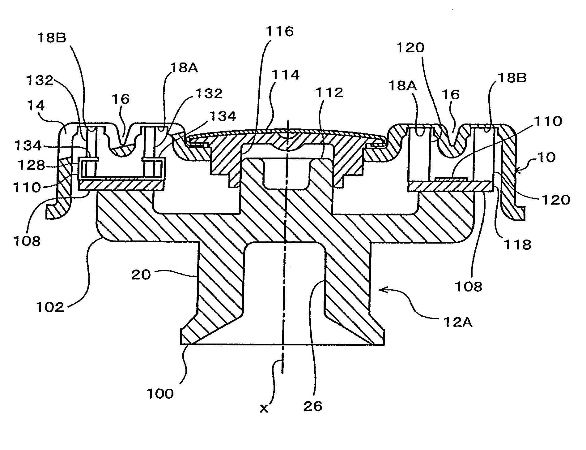
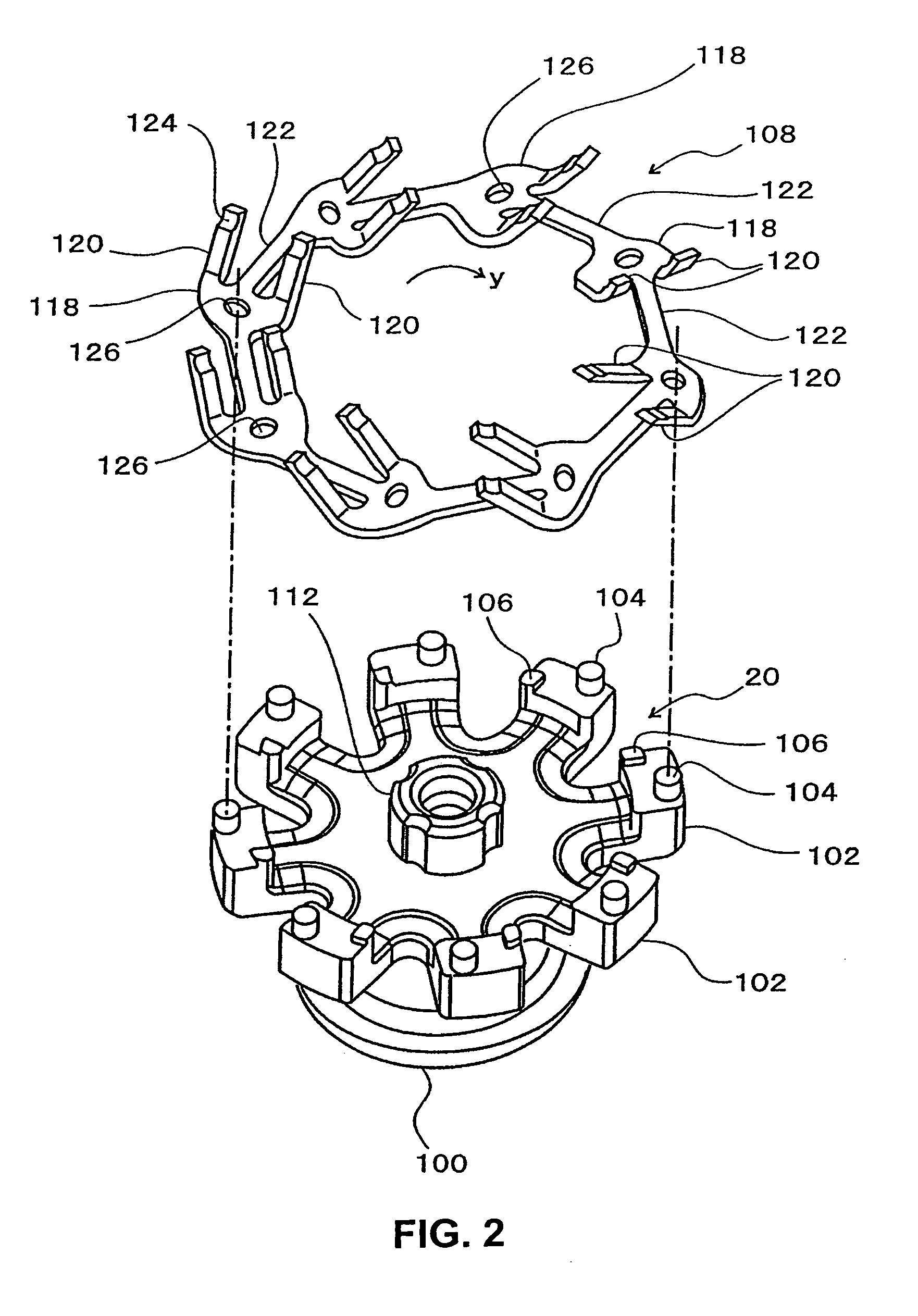
[0033]FIG. 1 shows, in vertical cross-section, the cutter unit according to one embodiment of the present invention, FIG. 2 is a perspective view of the inner cutter with the vibration element(s) removed, FIG. 3 is a perspective view of a part of the vibration element linking member, and FIGS. 4 to 6 illustrate, in vertical cross-section, the action of the vibration element, seen correspondingly along the line 10-10 line in FIG. 8.

[0034] In FIG. 1, the same reference numerals are applied to parts that are the same as in FIG. 8 to 10, and descriptions of such same parts are not repeated below. The main difference of the structure of the present invention from the structure of FIGS. 8 and 9 is that vibrating plates 132 are provided between the cutter blades 120 of the inner cutter 12A.

[0035] More specifically, the inner cutter main unit 20 of the inner cutter 12A is comprised of, as seen from FIG. 1, a substantially cup-shaped hub (central base unit) 100 and, as seen from FIG. 2, ei...


PUM


Abstract

A rotary electric shaver including a disc-shaped outer cutter 10, which is mounted in the upper part of a shaver main body housing therein a motor and has ring-shaped tracks 18 on the under (inner) surface thereof, and an inner cutter 12A, which has cutter blades 120 that elastically contact the ring-shaped tracks 18 of the outer cutter 10 from below and is rotated by the motor; and in this shaver, the inner cutter 12A has vibration elements 132 that travel in the ring-shaped tracks 18 and have a smaller spring constant, compared to the cutter blade 120, in the direction same as and opposite from the direction in which the cutter blades travel, and the vibration elements 132 vibrate and produce sound when, during shaving, they strike stoppers 134 provided near the vibration elements 132.

Description

BACKGROUND OF THE INVENTION [0001] 1. Field of the Invention [0002] The present invention relates to a rotary electric shaver in which a rotating inner cutter with its cutter blades elastically in contact with a ring-shaped track of a substantially disc-shaped outer cutter cuts whiskers (hair) entering into the hair introduction openings formed in the outer cutter. [0003] 2. Description of the Related Art [0004] When an electric shaver is used, vibration and noise are produced by the motor and drive system built installed in the shaver body, and, together therewith, noise (cutting noise, shaving noise, frictional noise, and the like) is produced by the vibration accompanying the friction between the outer cutter and the inner cutter and the vibration of the blades when the hair (whiskers, etc.) advanced between the outer cutter and the inner cutter is cut. In particular, the hair cutting noise and vibration noise caused by the outer cutter and the inner cutter are sensitively felt b...

Claims


Application Information

Patent Timeline
Patent Type & Authority Applications(United States)
IPC IPC(8): B26B19/14
CPCB26B19/141
Inventor OKABE, MASAKI
Owner IZUMI PROD CO
Learn More