Oil pumping unit using an electrical submersible pump driven by a circular linear synchronous three-phase motor with rare earth permananet magnet

a three-phase motor and electric submersible technology, applied in the direction of piston pumps, positive displacement liquid engines, borehole/well accessories, etc., can solve the problems of high initial investment as well as electrical consumption, shorten the service life of progressive cavity pumps, and increase the breakdown ra

Active Publication Date: 2007-05-24
WONG YEN HONG
View PDF6 Cites 19 Cited by
  • Summary
  • Abstract
  • Description
  • Claims
  • Application Information

AI Technical Summary

Problems solved by technology

It is easy to manage but its initial investment as well as its electrical consumption is high.
However, this progressive cavity pump lasts shorter with higher breakdown rate.
Beam pumping is durable with low breakdown rate, however, it has the drawbacks of complicated structure, low performance, and high electric energy consumption.

Method used


Image

  • Oil pumping unit using an electrical submersible pump driven by a circular linear synchronous three-phase motor with rare earth permananet magnet
  • Oil pumping unit using an electrical submersible pump driven by a circular linear synchronous three-phase motor with rare earth permananet magnet
  • Oil pumping unit using an electrical submersible pump driven by a circular linear synchronous three-phase motor with rare earth permananet magnet

Examples


Embodiment Construction

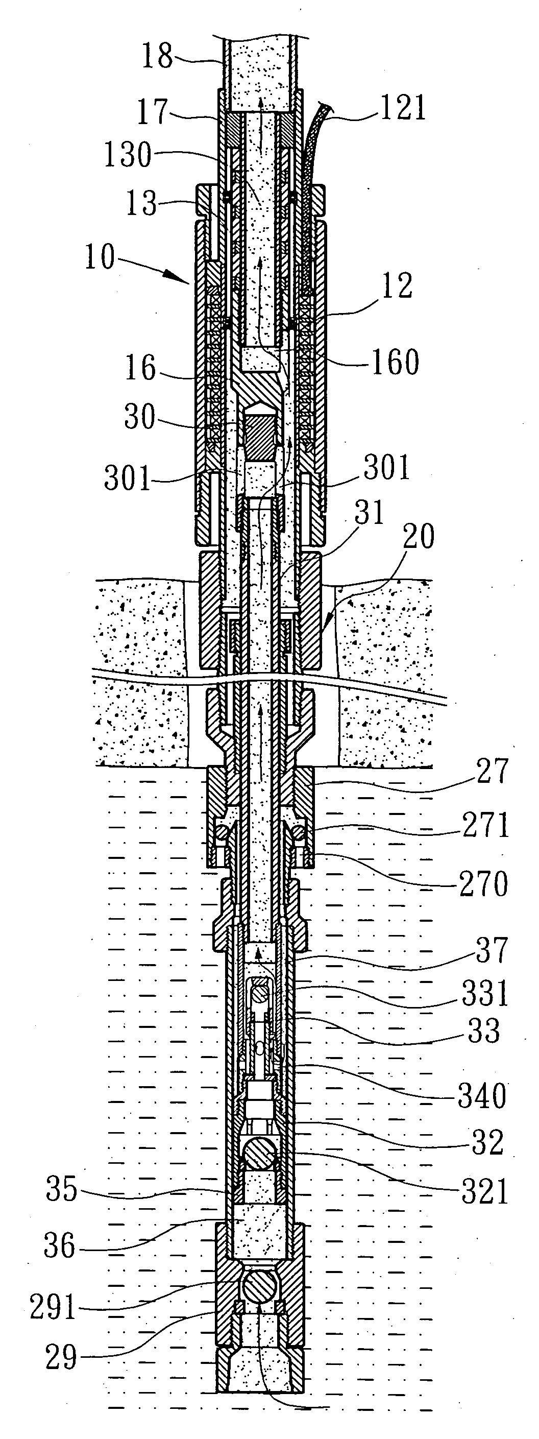
[0010] Referring to FIGS. 1-4, an oil pumping unit in accordance with the present invention is shown comprised of a motor 10 and a pump 20.

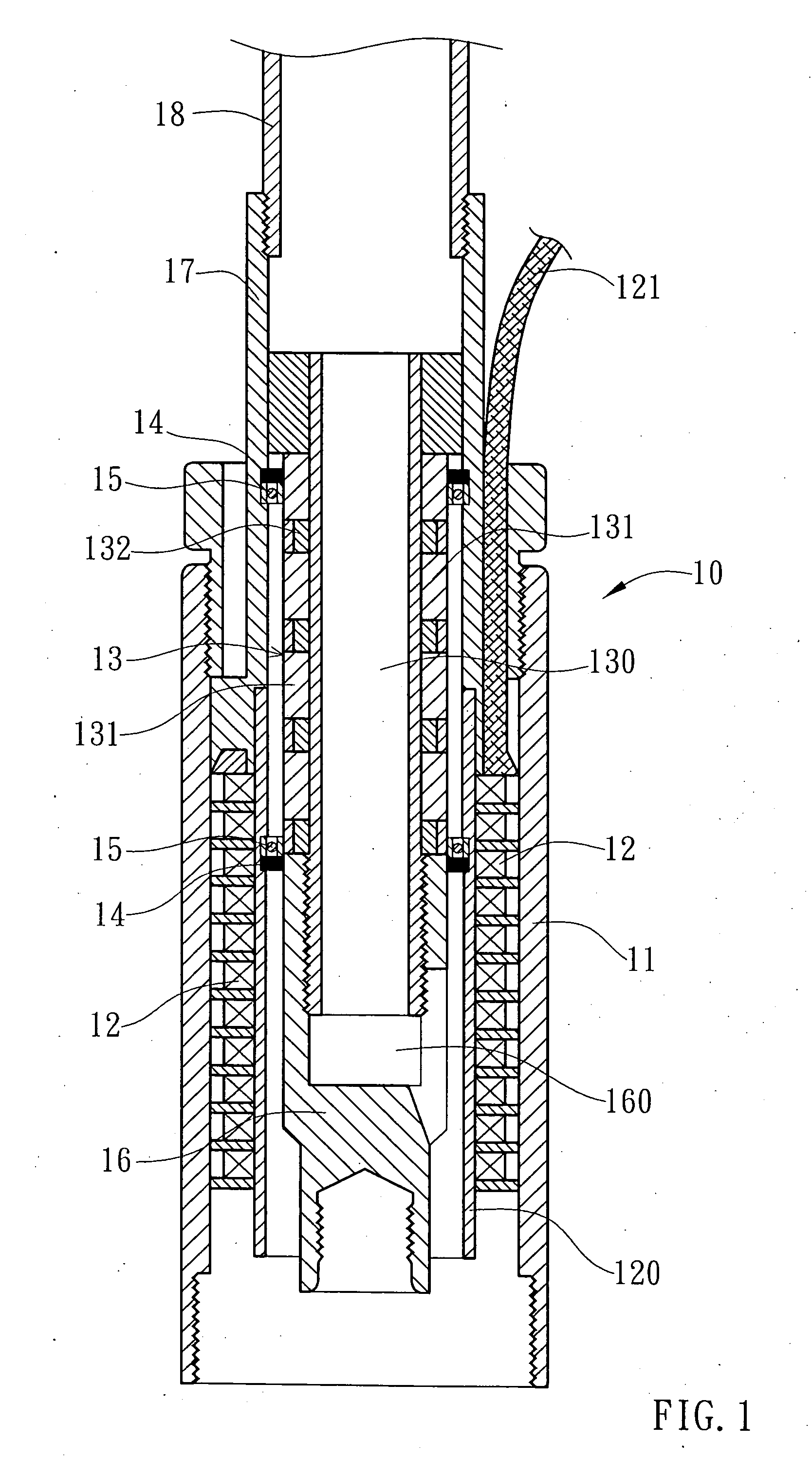
[0011] The motor 10 comprises a casing 11, a stator 12, and a mover 13. The mover 13 has an inner tube 130, which has outlet at the upper end to an oil delivery pipe 18 and connection at the lower end to a connector 16 that has an oil hole 160. The stator 12 has a power cable 121 connected to power supply. When power supply to the motor 10 is on through power cable 121, the mover 13 and the connected connector 16 are moved up and down.

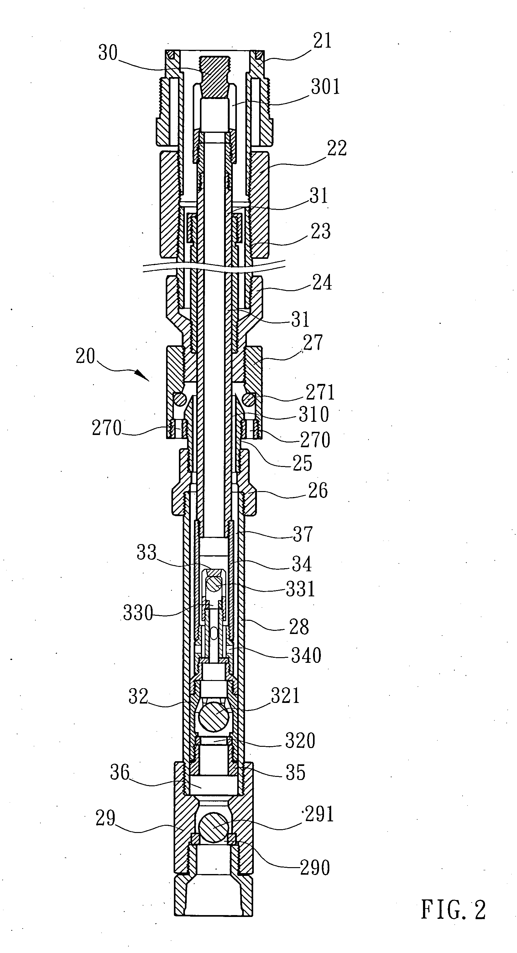
[0012] The pump 20 comprises a barrel formed of a motor connector 21, a socket connector 22, a plurality of inner sockets 23 and 25, a plurality of outer sockets 24 and 26, and an outer sleeve 28. An oil suction pipe 31 is mounted in the barrel of the pump 20. The oil suction pipe 31 has the top end mounted with a connector 30, which has an oil hole 301, and the bottom end connected to an inner sleeve 34, which ha...


PUM


Abstract

An oil pumping unit is disclosed to include a motor, which has a mover that moves alternatively up and down when the motor is electrically connected, and a pump, which has a barrel, an oil suction pipe mounted in the barrel, an inner sleeve, which is connected to the suction pipe and has installed therein a mixing valve, a movable valve and a piston, a bottom one-way oil intake valve, and an one-way mixing flow intake valve respectively arranged in such a manner that when the mover is operated to reciprocate the oil suction pipe, cruel oil is alternatively pumped through the one-way bottom oil intake valve and the one-way mixing flow intake valve to alternatively pass through the movable valve and the mixing valve to the ground.

Description

BACKGROUND OF THE INVENTION [0001] 1. Field of the Invention [0002] The present invention relates to an oil artificial lift unit for oil production and more particularly, to an oil artificial lift unit that uses an electrical submersible pump driven by a circular linear synchronous three-phase motor with rare earth permanent magnet. [0003] 2. Description of the Related Art [0004] An oil artificial lift device is a device that transforms rotary mechanical energy to linear mechanical energy and in turn pumps the oil from underground to ground surface. Presently there are many artificial lift technologies available. They have their advantages as well as shortcomings. Currently available electrical submersible pump uses a rotary motor to rotate a vane wheel, thereby pumping cruel oil to the ground surface. In general, an electrical submersible pump is used on large quantity oil production well. It is easy to manage but its initial investment as well as its electrical consumption is high...

Claims


Application Information

Patent Timeline
Patent Type & Authority Applications(United States)
IPC IPC(8): E21B43/00
CPCE21B43/128
Inventor SHEN, KUEI-HSIEN
Owner WONG YEN HONG
Why Eureka
Try Eureka