
Parallel uninterruptible power supply system

a power supply system and parallel technology, applied in the direction of parallel operation of dc sources, emergency power supply arrangements, transportation and packaging, etc., can solve the problems of increasing manufacturing costs, deteriorating product competitiveness, slow signal transmission, etc., to reduce manufacturing costs, shorten response time, and speed up signal transmission rate

Inactive Publication Date: 2007-05-24
DELTA ELECTRONICS INC
View PDF2 Cites 57 Cited by
  • Summary
  • Abstract
  • Description
  • Claims
  • Application Information

AI Technical Summary

Benefits of technology

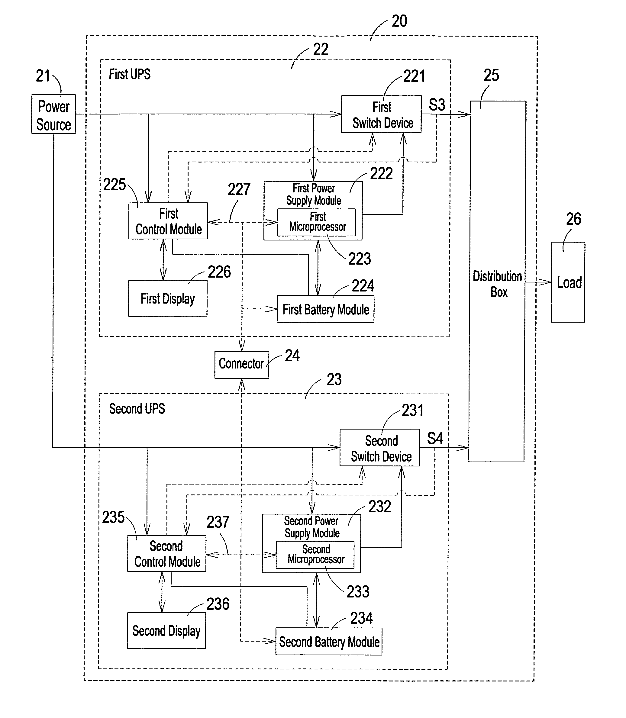
The present invention provides a parallel uninterruptible power supply system that can communicate with each other without the need of a communication port, resulting in faster signal transmission and a shorter response time. The system includes two uninterruptible power supplies and a connector that allows direct communication between the two power supplies. This eliminates the need for an internal communication chip and reduces manufacturing costs. Additionally, the system can communicate with each other using signal transmission lines, allowing for multilateral communication between the power supplies.

Problems solved by technology

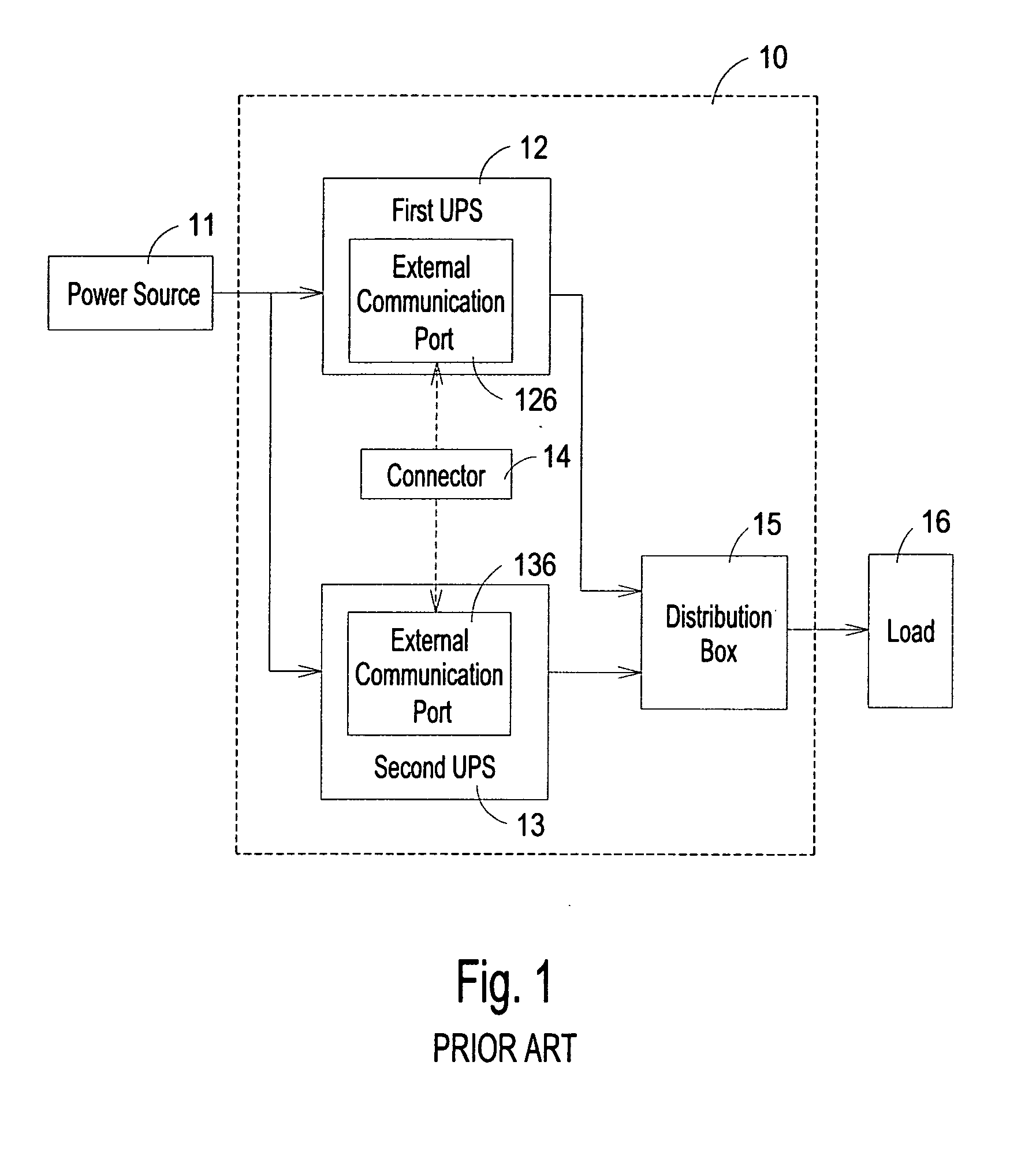
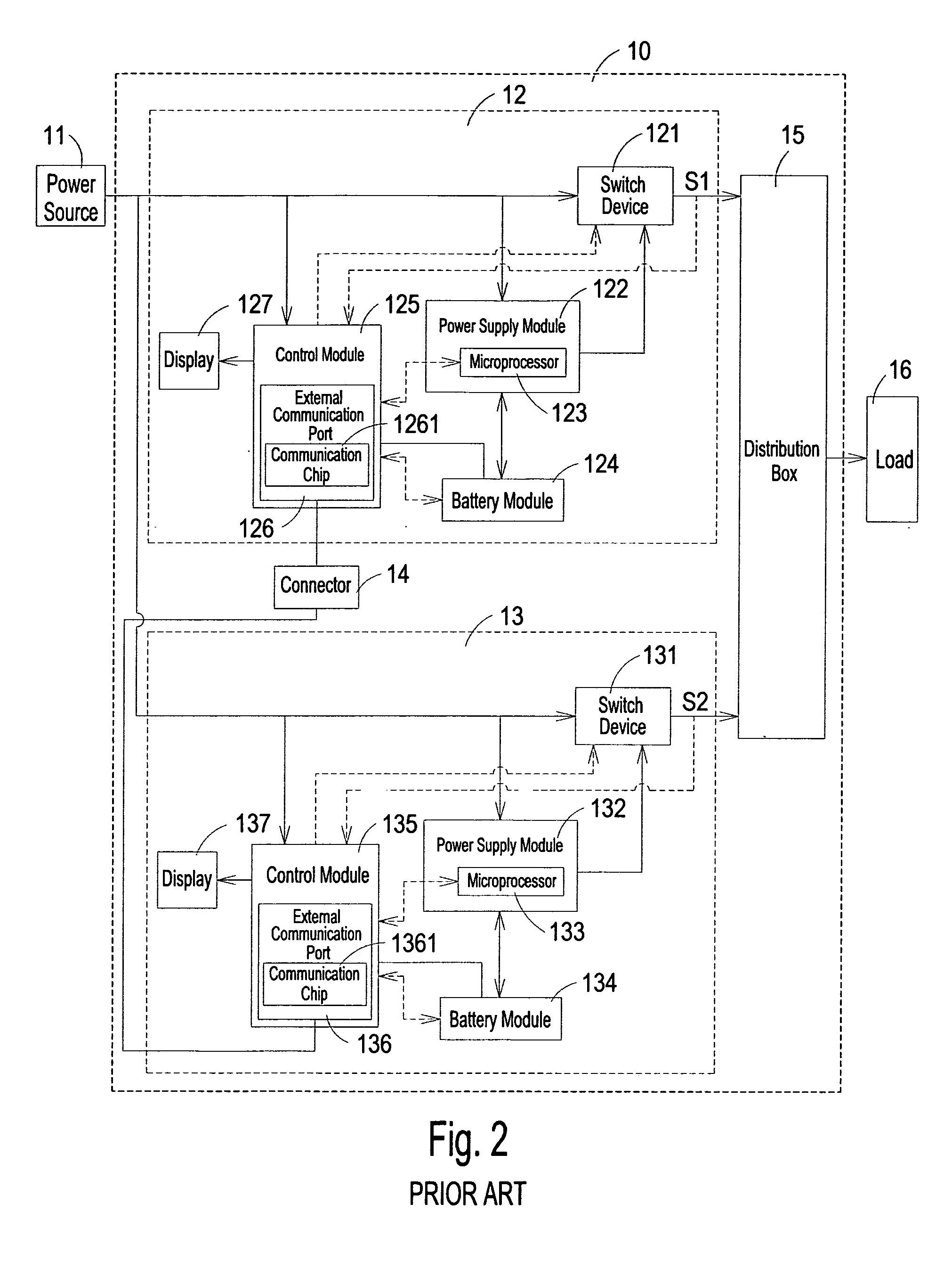
Such communication mode would result in a long communication path and cause the slowness of the signal transmission, which would in turn prolong the response time of the entire uninterruptible power supply system 10.
More disadvantageously, both of the external communication ports 126, 136 have complicated circuit architecture and require an internal communication chip 1261, 1361 to conduct signal transmission, which would increase the manufacturing cost and deteriorate the product competitiveness.

Method used


Image

  • Parallel uninterruptible power supply system
  • Parallel uninterruptible power supply system
  • Parallel uninterruptible power supply system

Examples


Embodiment Construction

[0022] Several preferred embodiments embodying the features and advantages of the present invention will be expounded in following paragraphs of descriptions. It is to be realized that the present invention is allowed to have various modification in different respects, all of which are without departing from the scope of the present invention, and the description herein and the drawings are to be taken as illustrative in nature, but not to be taken as limitative.

[0023]FIG. 3 illustrates a detailed circuit block diagram of a parallel UPS system according to a first preferred embodiment of the present invention. As shown in FIG. 2, a parallel uninterruptible power supply system20 is configured to receive an input AC power from a power source 21 at one end and connect to a load 26 at the other end. The parallel UPS system 20 is made up of a first UPS 22, a second UPS 23, a connector 24, and a distribution box 25. The first UPS 22 and the second UPS 23 are configured to perform rectifi...


PUM


Abstract

Provided is a parallel uninterruptible power supply system including a first uninterruptible power supply and a second uninterruptible power supply connected in parallel with each other, and a connector interconnecting a first signal transmission line of the first uninterruptible power supply and a second signal transmission line of the second uninterruptible power supply. A first control module of the first uninterruptible power supply can directly receive data signal outputted from a second power supply module and a second battery module of the second uninterruptible power supply, and a second control module of the second uninterruptible power supply can directly receive data signal outputted from a first power supply module and a first battery module of first uninterruptible power supply, so that the first uninterruptible power supply and the second uninterruptible power supply can communicate directly with each other.

Description

FIELD OF THE INVENTION [0001] The present invention is related to an uninterruptible power supply system, and more particularly to a parallel uninterruptible power supply system. BACKGROUND OF THE INVENTION [0002] Uninterruptible power supply (UPS) is an emergent power supply device connected between a power source and a load, in which the power source can be a commercial AC power supply or any other AC power source. The uninterruptible power supply is configured to supply the power required for powering a load in an emergent condition so as to ensure the normal operation for the load when the power source becomes abnormal. [0003] In order to protect important electronic equipment with more efficiency and safety, UPS has been extensively employed to ensure the normal operation for various electronic devices. More particularly, a parallel UPS system has been testified to be the best choice for providing high quality, high continuity electric power to electronic devices that are vulne...

Claims


Application Information

Patent Timeline
Patent Type & Authority Applications(United States)
IPC IPC(8): H02J9/00
CPCH02J1/10H02J9/061H02J1/001
Inventor LIN, HUNG-CHIEHLIAO, JEN-CHUANLUNG, KUO-CHIANG
Owner DELTA ELECTRONICS INC
Learn More