Method and apparatus for interconnect diagnosis

a technology of interconnection and diagnosis method, applied in the direction of electric connection testing, measurement devices, instruments, etc., can solve the problems of inability of service engineers to isolate the location of such faults, difficult to identify the location of faults, and high cos

Active Publication Date: 2007-05-24
ORACLE INT CORP
View PDF9 Cites 13 Cited by
  • Summary
  • Abstract
  • Description
  • Claims
  • Application Information

AI Technical Summary

Benefits of technology

[0009] In one embodiment, additional points of visibility are added to functional signal lines of a system. Additional points of visibility may be created by adding sense lines in close proximity to functional trace lines which are to be monitored. Using parasitic coupling between the sense lines and functional traces, a small portion of the functional signal may be redirected to a monitoring device. Based upon the characteristics of the signal detected by the monitoring device, the location of a fault may be determined, or otherwise narrowed to a particular region.
[0010] In one embodiment, a system includes a first component configured to communicate with a second component via a signal path including one or more signal traces. Sense signal lines are manufactured such that at some point they are in close proximity to a signal trace which is to be monitored. The sense signal lines are configured to use parasitic coupling to redirect a portion of a signal conveyed via a signal trace to a monitoring component. The first component is configured to convey a test signal indicative of a type of test via the signal path, and a reference signal to the monitoring component. The monitoring component is configured to utilize the reference signal to ascertain a presence or absence, or characteristics of a received redirected signal.

Problems solved by technology

When an error is detected, identifying the location of a fault can be quite difficult.
A fault could be due to a short, a failure of a trace line, a faulty connector, and so on.
Often times, a service engineer may not be able to isolate the location of such a fault and may simply attempt to correct the problem via trial and error.
As may be appreciated, such an approach is fairly inefficient, costly, and may lead to increased downtime for a customer.
Should the system 100 fail, or otherwise indicate an error, a fault in communication within the system 100 may be the cause.
Unfortunately, determining a location of the fault may be very difficult.
Consequently, while it may be possible to determine that a problem exists, the location of a given fault cannot be determined without additional information.
However, such approaches do not provide any certainty.

Method used


Image

  • Method and apparatus for interconnect diagnosis
  • Method and apparatus for interconnect diagnosis
  • Method and apparatus for interconnect diagnosis

Examples


Embodiment Construction

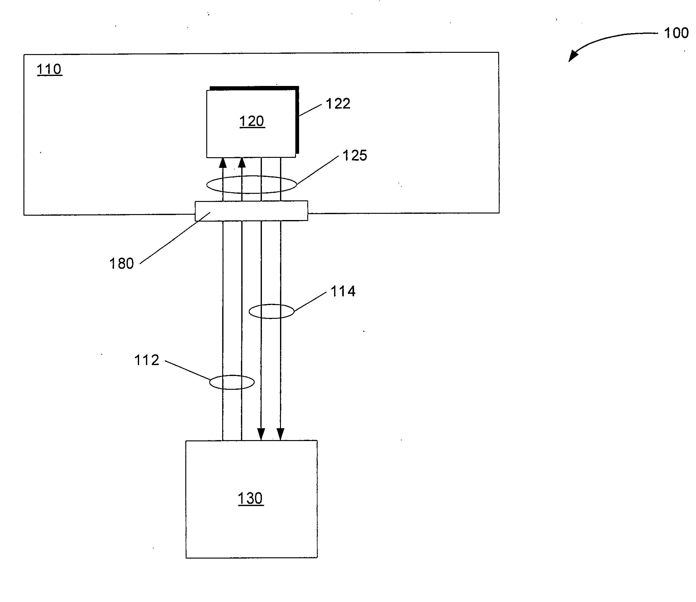
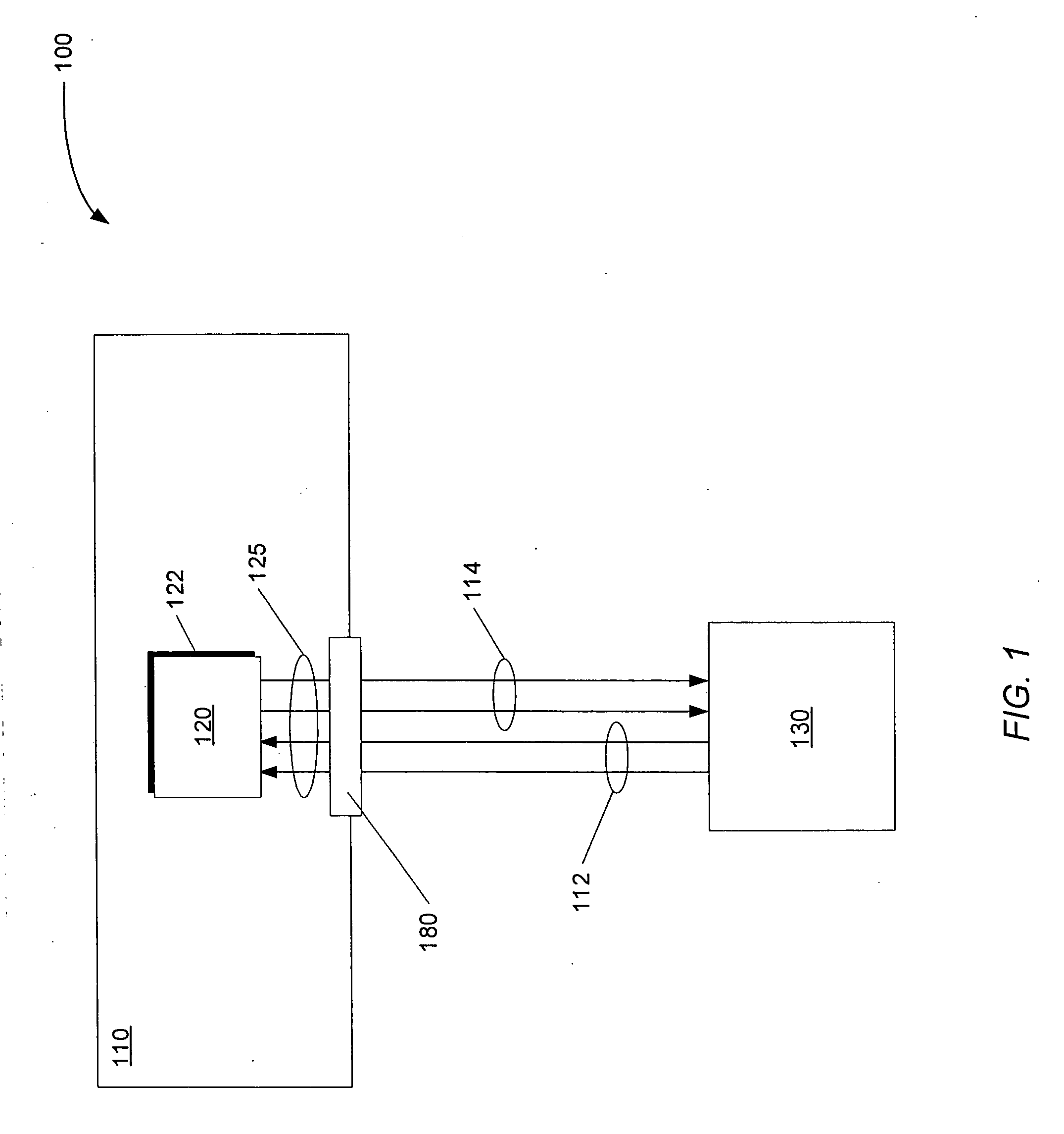
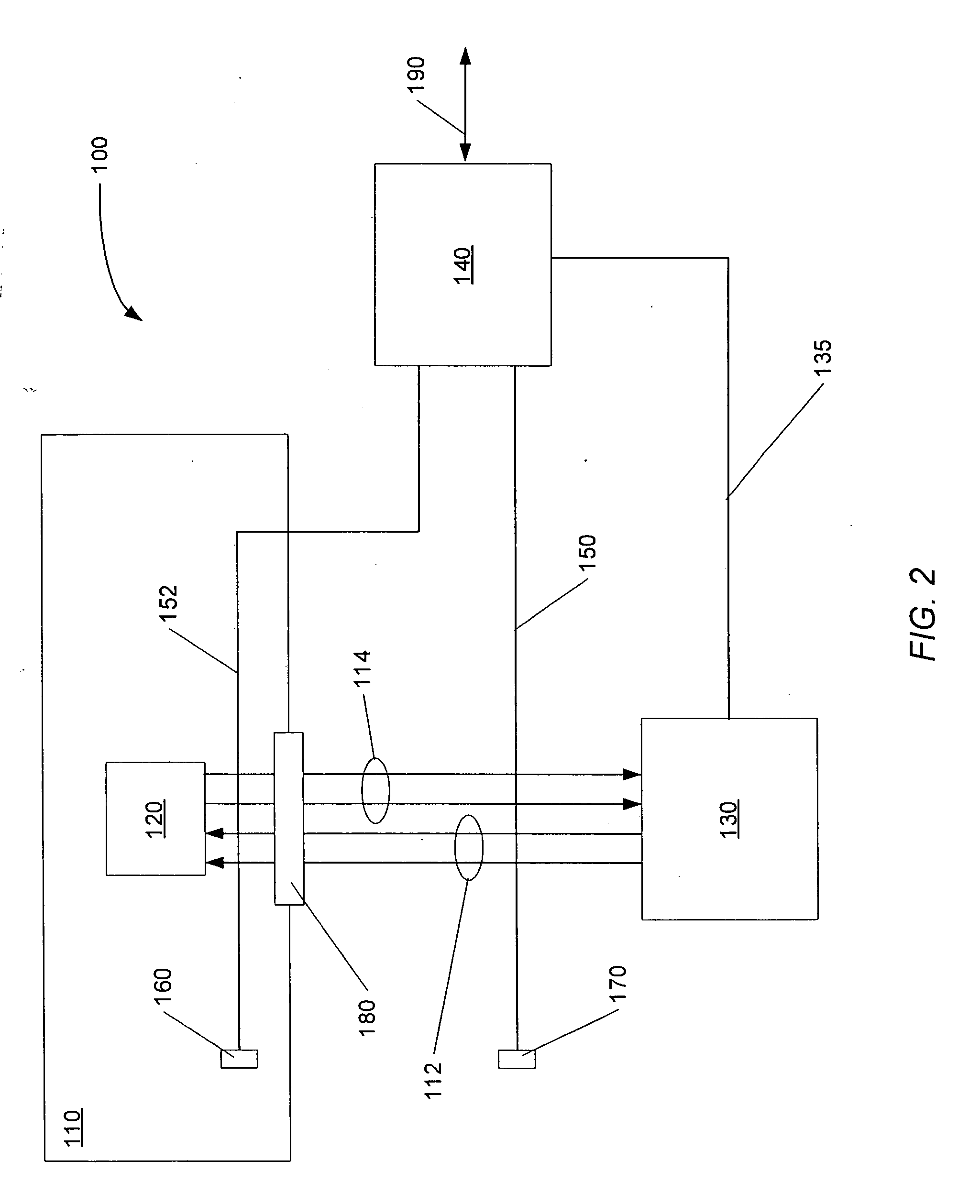
[0025] Turning now to FIG. 2, one embodiment of a system configured to provide additional information concerning the location of a in the event of failure is illustrated. Generally speaking, system 100 of FIG. 2 has been modified by adding additional receivers to the signal network. The manner in which the additional receiver is added is configured to have minimal (and controlled) impact on signal integrity and timing. FIG. 2 includes components similar to those of FIG. 1, which are similarly numbered. In addition, the system 100 of FIG. 2 includes a component 140 (e.g., an instrumentation device) which is configured to monitor communications between components 120 and 130. It is noted that component 140 may also be configured to monitor other signals and components than those which are shown. Each of the components depicted in FIG. 2 may be part of a single chip and / or package, or a larger interconnected system.

[0026] In the example shown, component 140 includes a signal sense lin...


PUM


Abstract

A system configured to detect faults in signal lines. A system includes a first component configured to communicate with a second component via a signal path including one or more signal traces. Sense signal lines are manufactured such that at some point they are in close proximity to a signal trace which is to be monitored. The sense signal lines are configured to use parasitic coupling to redirect a portion of a signal conveyed via a signal trace to a monitoring component. The first component is configured to convey a test signal indicative of a type of test via the signal path, and a reference signal to the monitoring component. The monitoring component is configured to utilize the reference signal to ascertain a presence or absence, or characteristics of a received redirected signal. The monitoring component may optionally utilize a locally generated reference signal.

Description

BACKGROUND [0001] 1. Field of the Invention [0002] This invention is related to the field of signal transmission paths and, more particularly, to diagnosing interconnect faults. [0003] 2. Description of the Related Art [0004] Computing systems and components typically have numerous communication paths which must remain operable for the system as a whole to operate correctly. Such communication paths occur within given assemblies (e.g., a single printed circuit board, device, or chip), and across such assemblies as well. For example, multiple boards may be coupled to communicate via connectors. When an error is detected, identifying the location of a fault can be quite difficult. A fault could be due to a short, a failure of a trace line, a faulty connector, and so on. Often times, a service engineer may not be able to isolate the location of such a fault and may simply attempt to correct the problem via trial and error. For example, the engineer may first replace an entire printed c...

Claims


Application Information

Patent Timeline
Patent Type & Authority Applications(United States)
IPC IPC(8): G01R31/04
CPCG01R31/046G01R31/2812G01R31/2853G01R31/312G01R31/70
Inventor MIROV, RUSSELL N.DAVIDSON, HOWARD L.
Owner ORACLE INT CORP
Why Eureka
Try Eureka