
Transmission and reception parameter control

Active Publication Date: 2007-05-24
ARRIS ENTERPRISES LLC
View PDF99 Cites 65 Cited by
  • Summary
  • Abstract
  • Description
  • Claims
  • Application Information

AI Technical Summary

Benefits of technology

[0010] In one exemplary embodiment of the present invention, a method for implementing transmission parameter control at a transmitting station is described. The exemplary method comprises querying a transmission parameter control module for a transmission schedule. The transmission schedule comprises a

Problems solved by technology

The wireless link may be susceptible to, for example, interference from other access points, other radio transmitting devices, or disturbances in the environment of the wireless link between the access point and the remote receiving node.
The interference may be to such a degree as to degrade the wireless link, for example, by forcing communication at a lower data rate.
The interference also may be sufficiently strong enough to completely disrupt the wireless link.
Current methods that provide switching among antenna configurations, such as diversity antennas, and previous methods of controlling antenna segments are unable to effectively minimize the interference from other access points, other radio transmitting devices, or disturbances in the environment of the wireless link between the access point and the remote receiving node.
The trial-and-error approach is inefficient as it generally requires transmission on a “bad” antenna configuration to determine the poor quality of that antenna configuration.
Further, the trial-and-error approach becomes increasingly inefficient with a large number of antenna configurations.
Such measurements can take a significant amount of time to compute, and may require large numbers of data packets to be transmitted before the measurements can be performed.

Method used


Image

  • Transmission and reception parameter control
  • Transmission and reception parameter control
  • Transmission and reception parameter control

Examples


Embodiment Construction

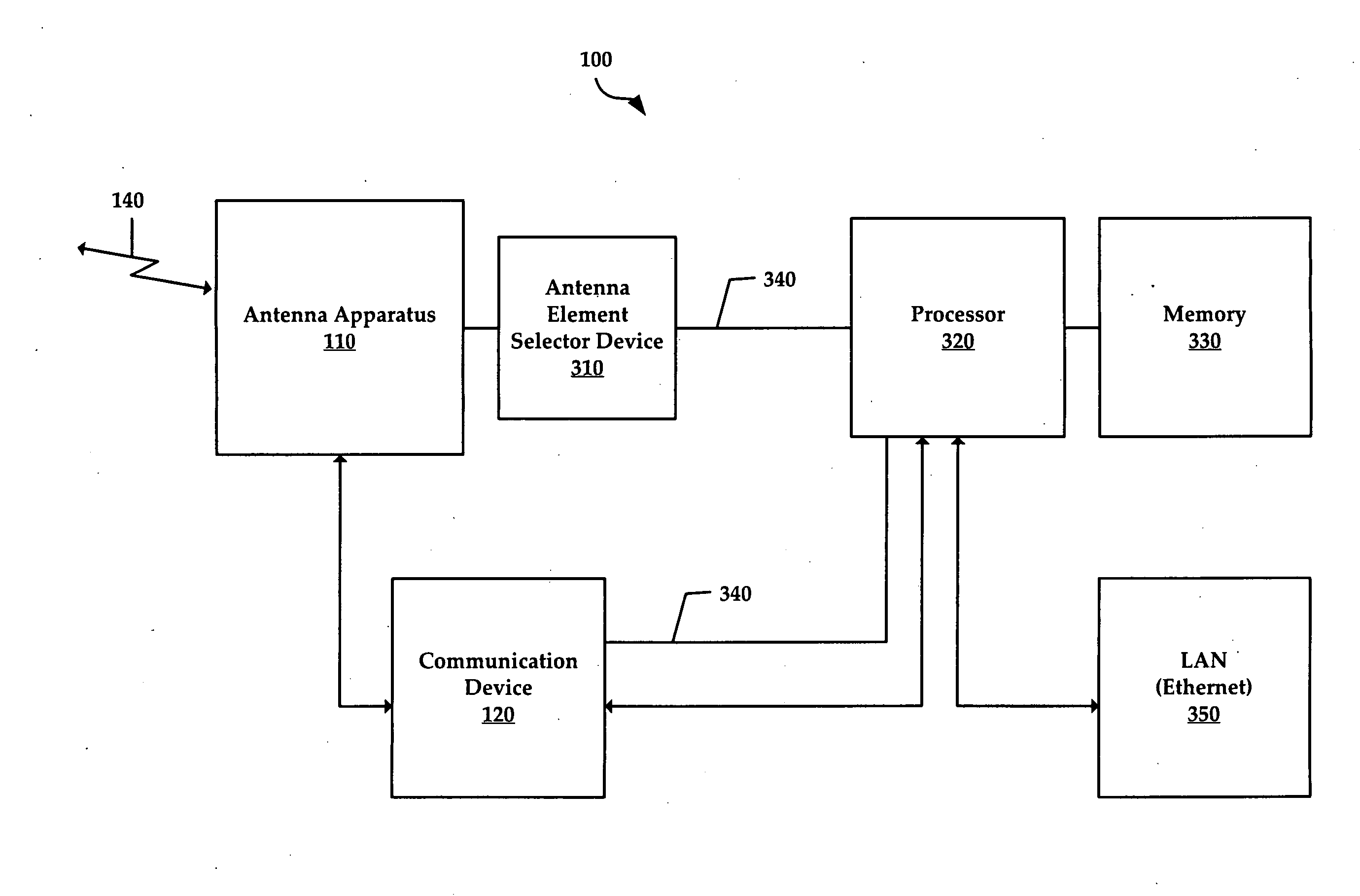
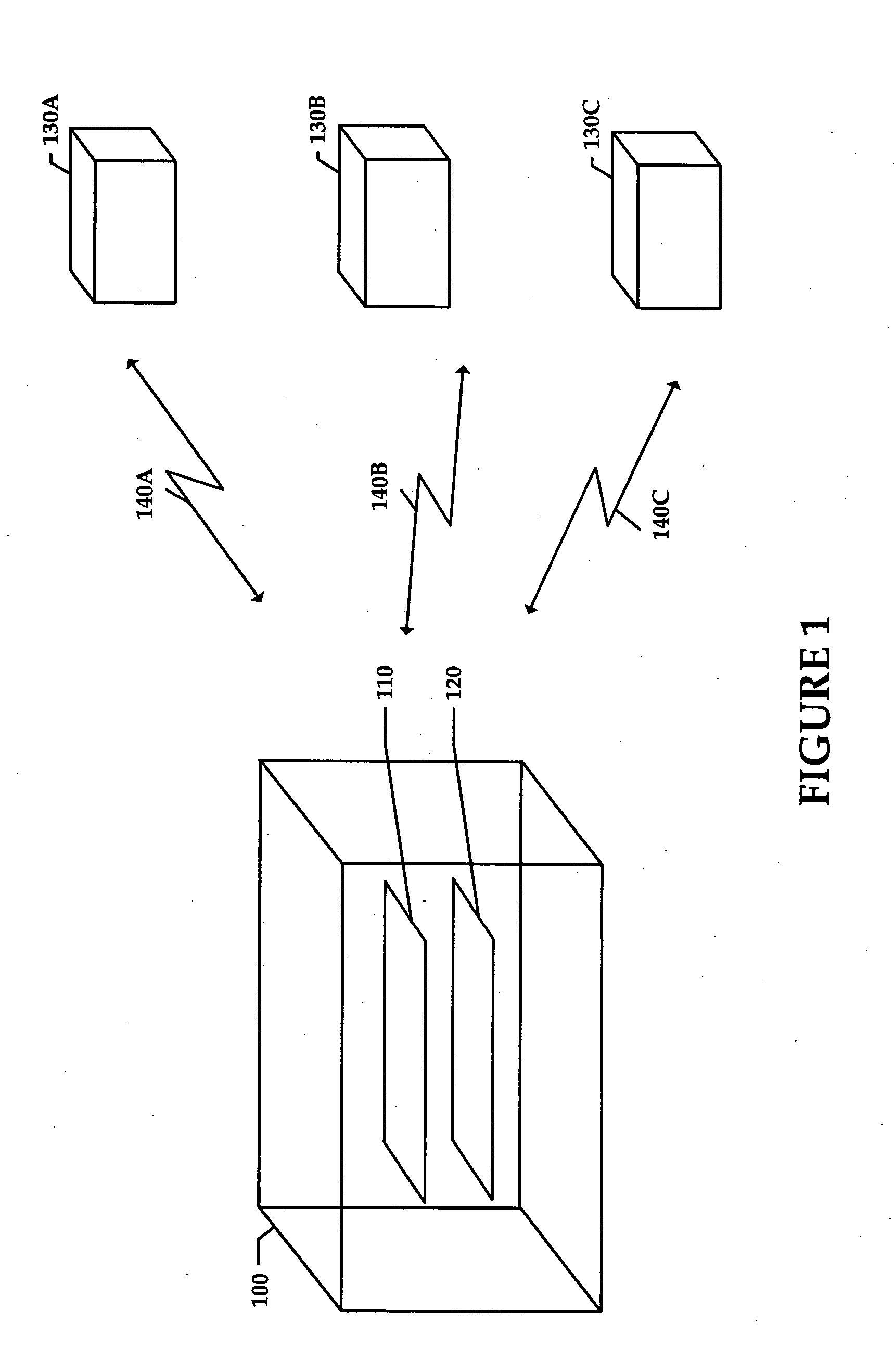
[0023] A system for a wireless (e.g., radio frequency or RF) link to a remote receiving device in accordance with an embodiment of the present invention generally includes a communication device for generating an RF signal, an antenna apparatus with selectable antenna elements for transmitting and / or receiving the RF signal, and a processor for controlling the communication device and the antenna apparatus. The communication device (or a device communicatively coupled thereto) converts data packets into RF at one of a plurality of selectable physical data rates. Each antenna element of the antenna apparatus may provide gain (with respect to an isotropic antenna) and a directional radiation pattern and may be electrically selected (e.g., switched on or off) so that the antenna apparatus may form a configurable (i.e., direction agile) radiation pattern. The processor may select the antenna configuration so that interference may be minimized in the wireless link to the remote receiving...


PUM


Abstract

A system and method for implementing transmission parameter control at a transmitting station is described. The exemplary system and method comprises querying a transmission parameter control module for a transmission schedule. The transmission schedule comprises at least one schedule entry defining a set of transmission parameter controls as they pertain to a destination address. At least one packet of data is then transmitted to the destination address according to the transmission parameters controls of at least one schedule entry from the transmission schedule. A system and method for selecting an antenna configuration corresponding to a next transmission of packet data is also disclosed.

Description

CROSS-REFERENCE TO RELATED APPLICATIONS [0001] The present application is a continuation-in-part and claims the priority benefit of U.S. patent application No. 11 / 180,329 filed Jul. 12, 2005 and entitled “System and Method for Transmission Parameter Control for an Antenna Apparatus with Selectable Elements,” which claims the priority benefit of U.S. provisional patent application No. 60 / 602,711 filed Aug. 18, 2004 and entitled “Planar Antenna Apparatus for Isotropic Coverage and QoS Optimization in Wireless Networks,” U.S. provisional patent application No. 60 / 603,157 filed Aug. 18, 2004 and entitled “Software for Controlling a Planar Antenna Apparatus for Isotropic Coverage and QoS Optimization in Wireless Networks,” and U.S. provisional patent application number 60 / 625,331 filed Nov. 5, 2004 and entitled “Systems and Methods for Improved Data Throughput in Wireless Local Area Networks”; the present application also claims the priority benefit of U.S. provisional patent application...

Claims


Application Information

Patent Timeline
IPC IPC(8): H01Q9/04H04L45/74
CPCH01Q21/29H04B7/061H04B17/318H04B17/24H04B7/0689H01Q1/2291H04L45/74H04W72/1263
Inventor KISH, WILLIAMSHTROM, VICTORCHANAK, JOHN
Owner ARRIS ENTERPRISES LLC
Features
  • Generate Ideas
  • Intellectual Property
  • Life Sciences
  • Materials
  • Tech Scout
  • Unparalleled Data Quality
  • Higher Quality Content
  • 60% Fewer Hallucinations
Learn More