
Controlling optical power and extincation ratio of a semiconductor laser

a technology of optical power and extinction ratio, which is applied in the direction of semiconductor lasers, instruments, optical elements, etc., can solve the problems of significant diminishing the performance of optical transceivers in which the semiconductor lasers are employed, increasing temperature, and certain characteristics of the semiconductor lasers that may change with temperatur

Inactive Publication Date: 2007-05-24
INTEL CORP
View PDF28 Cites 40 Cited by
  • Summary
  • Abstract
  • Description
  • Claims
  • Application Information

AI Technical Summary

Problems solved by technology

Furthermore, multiple SFF modules may be included in the same line card or network device, which may further promote an increase in temperature.
A challenge is that certain characteristics of the semiconductor lasers may change with temperature.
If unmitigated, changes in one or more of these parameters may significantly diminish performance of optical transceivers in which the semiconductor lasers are employed.
Potential drawbacks of such an approach are that the provision of the memory to store the look-up table may increase manufacturing cost, and / or that obtaining the data to populate the look-up table may be costly to obtain, difficult to obtain, inconvenient to obtain, and / or inaccurate.

Method used


Image

  • Controlling optical power and extincation ratio of a semiconductor laser
  • Controlling optical power and extincation ratio of a semiconductor laser
  • Controlling optical power and extincation ratio of a semiconductor laser

Examples


Embodiment Construction

[0018] In the following description, numerous specific details are set forth. However, it is understood that embodiments of the invention may be practiced without these specific details. In other instances, well-known circuits, structures and techniques have not been shown in detail in order not to obscure the understanding of this description.

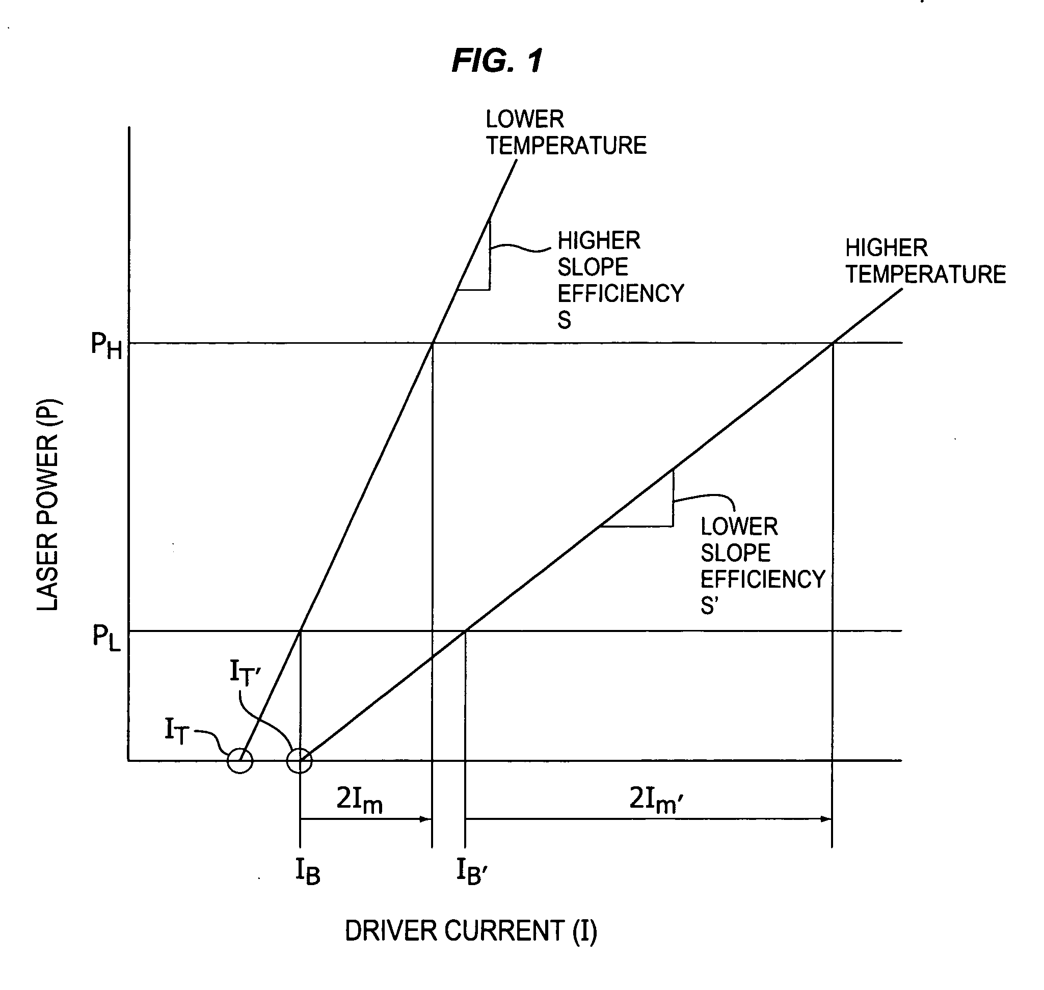
[0019]FIG. 1 is a plot showing representative laser output power versus laser input drive current characteristics for a semiconductor laser at two different temperatures, according to one or more embodiments. Vertical cavity surface emitting laser (VCSELs) and Fabry-Perot lasers tend to exhibit similar characteristics. Other types of semiconductor lasers may also have a slope efficiency and / or threshold current that may depend upon temperature.

[0020] The plot shows driver current (I) that is provided to the laser on the horizontal axis, and laser output power (P) that corresponds to the driver current on the vertical axis. Two different “cur...


PUM


Abstract

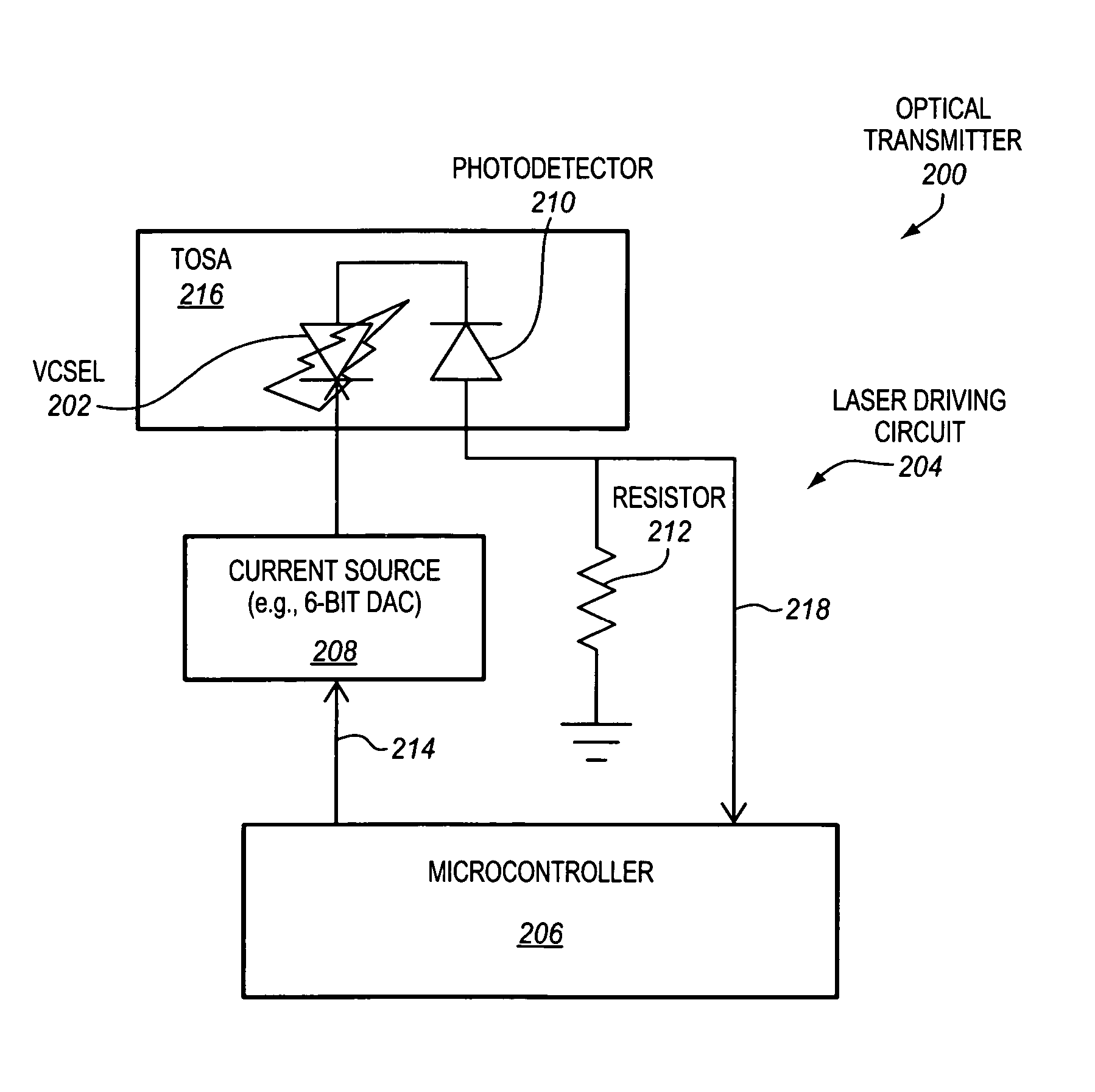
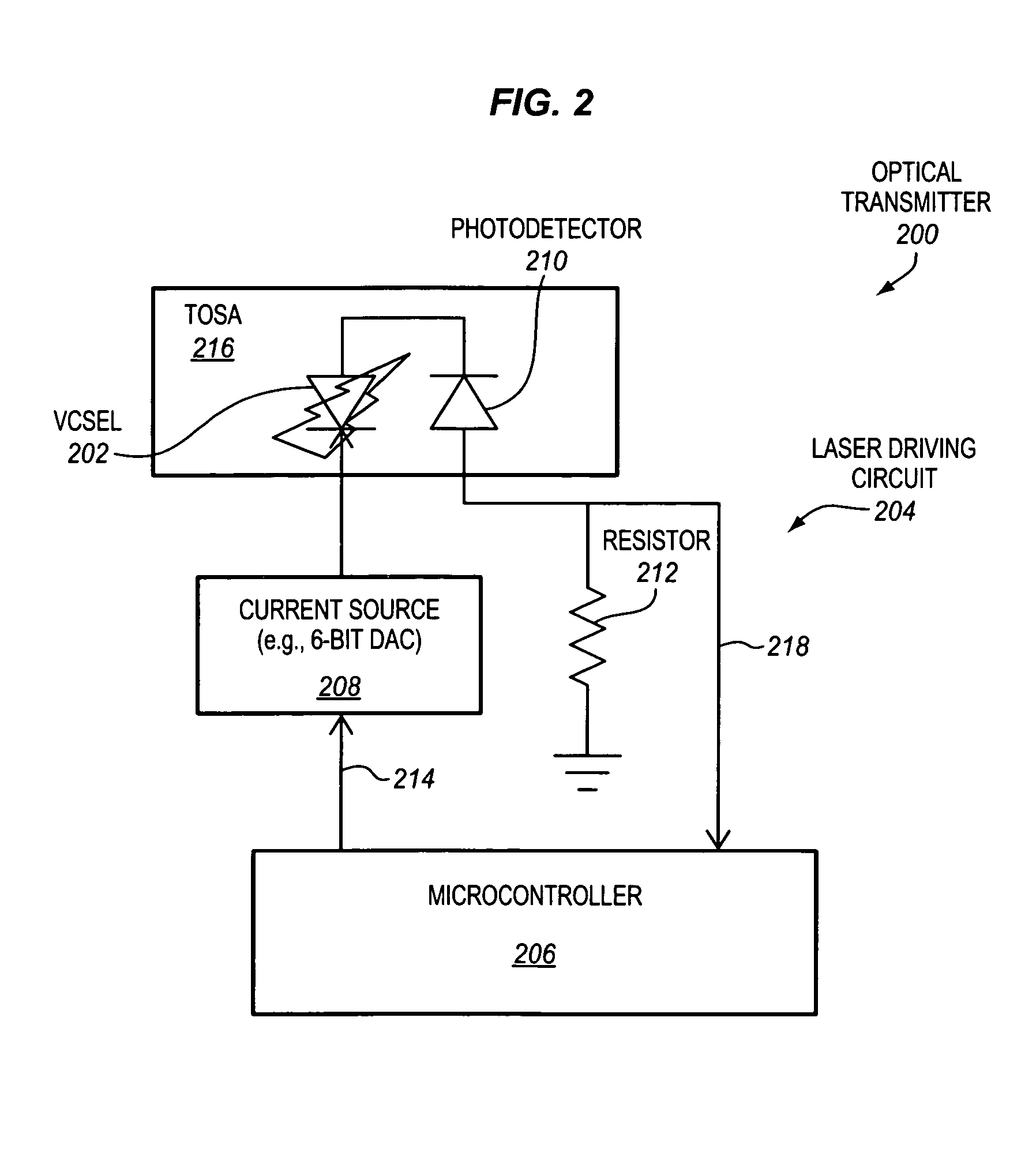
Disclosed herein are methods, apparatus, and systems to achieve substantially constant optical power and / or extinction ratio for a semiconductor laser. In one aspect, a microcontroller of an optical transmitter may adjust an electrical current that is provided to a semiconductor laser based at least in part on a comparison of a first measured optical power of light emitted by the semiconductor laser and a predetermined target optical power. The microcontroller may then determine an electrical current that is capable of giving the semiconductor laser a substantially constant extinction ratio by evaluating an equation with the first measured optical power and a second optical power measured after the controller adjusts the electrical current.

Description

RELATED APPLICATIONS [0001] The present application is related to co-pending U.S. patent application Ser. No. 11 / 008,905, filed on Dec. 10, 2004.BACKGROUND [0002] 1. Field [0003] One or more embodiments of the invention relate to the control of semiconductor lasers. In particular, one or more embodiments of the invention relate to the control of optical power and / or extinction ratio of semiconductor lasers. [0004] 2. Background Information [0005] Semiconductor lasers are used in a wide variety of applications. In particular, semiconductor lasers are integral components in optical communication systems where a beam modulated with large amounts of information may be communicated great distances at the speed of light over optical fibers as well as short reach distances such as from chip-to-chip in a computing environment. [0006] The semiconductor lasers are commonly operated at different temperatures. One reason for which the temperature of the semiconductor lasers may change is due to...

Claims


Application Information

Patent Timeline
IPC IPC(8): H01S3/00
CPCG02B6/4204H01S5/02212H01S5/02284H01S5/0617H01S5/0683H01S5/06832H04B10/564H01S5/02251
Inventor WANG, FRANKLIU, CHIEN-CHANGCHENG, HENGJUXU, LEE
Owner INTEL CORP
Learn More