Gas turbine bucket with cooled platform leading edge and method of cooling platform leading edge

a technology of turbine buckets and bucket heads, applied in the direction of engine fuction, leakage prevention, machines/engines, etc., can solve the problems of uncool buckets, low cycle fatigue and creep, and general limited film cooling, so as to minimize the impact on engine performance

Active Publication Date: 2007-05-24
GENERAL ELECTRIC CO
View PDF23 Cites 27 Cited by
  • Summary
  • Abstract
  • Description
  • Claims
  • Application Information

AI Technical Summary

Benefits of technology

[0003] The present invention provides a unique solution to the above problem by actively cooling the bucket platform leading edge such that the bucket meets life requirements while minimizing the impact on engine performance. Active cooling is provided by directing cooling media to a cavity extending along the platform leading edge. Thus, the invention may be embodied in a turbine bucket having an airfoil portion and a root portion with a substantially planar platform at an interface between the airfoil portion and the root portion, a platform cooling arrangement including a cavity extending along the forward portion of the platform, at least one inlet bore extending from a source of cooling medium to said cavity and at least one outlet opening for expelling cooling medium from said cavity.

Problems solved by technology

As firing temperatures increase, bucket platforms, which in the past have been un-cooled, exhibit distress, such as oxidation, low cycle fatigue and creep.
Film cooling has been used more recently to help cool the platforms, but film cooling is generally limited to the aft portions of the platform where the gas path flow has been accelerated sufficiently to drop the static pressure to a level where there is sufficient supply pressure to have positive film flow without hot gas ingestion.
Platform leading edges are in a region where there is insufficient pressure to utilize film cooling but is also a region where there is distress due to high temperatures.

Method used


Image

  • Gas turbine bucket with cooled platform leading edge and method of cooling platform leading edge
  • Gas turbine bucket with cooled platform leading edge and method of cooling platform leading edge
  • Gas turbine bucket with cooled platform leading edge and method of cooling platform leading edge

Examples


Embodiment Construction

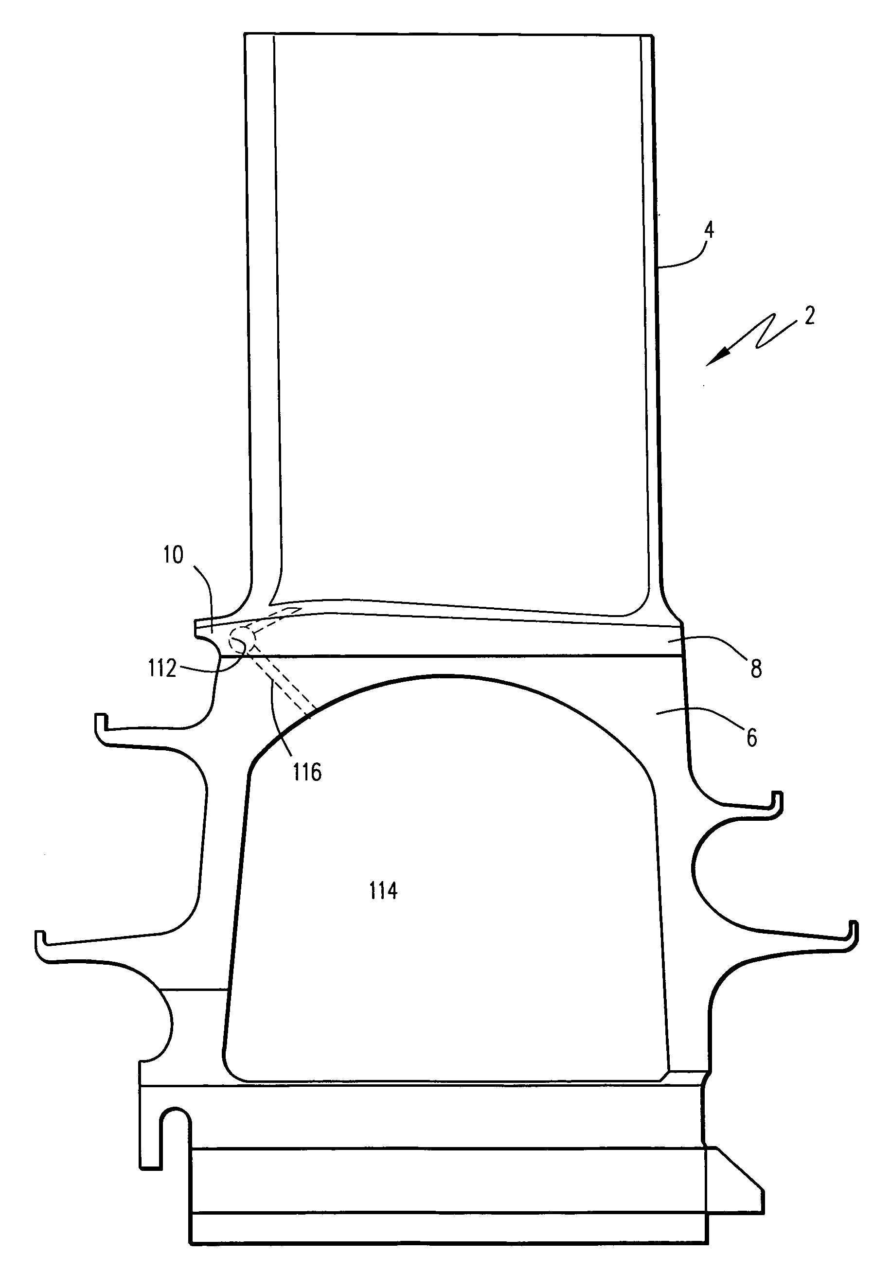
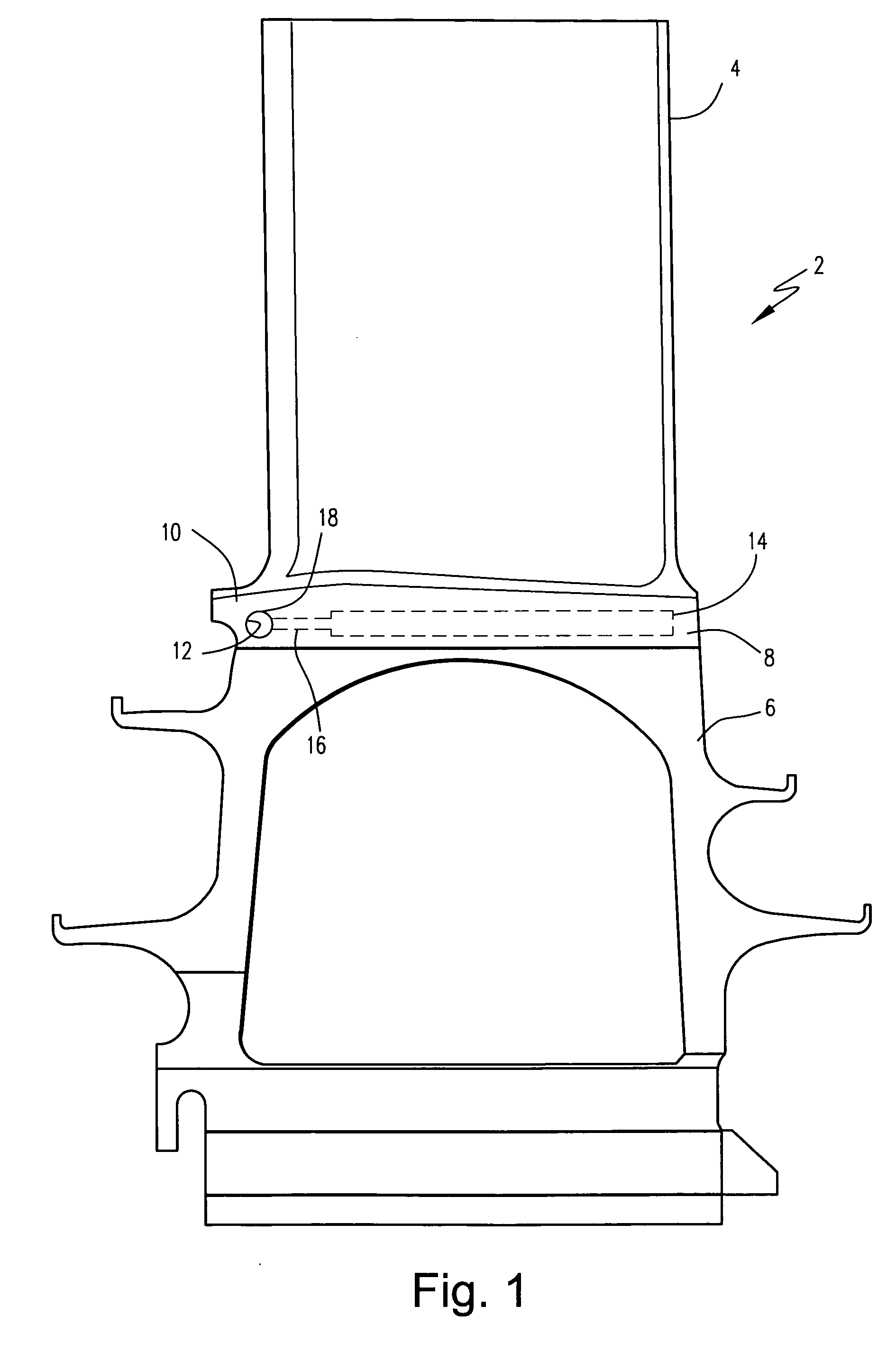
[0009] The leading edges of bucket platforms have begun to exhibit distress such as oxidation, low cycle fatigue and creep as firing temperatures have increased. There is insufficient cooling pressure ratio to film cool the bucket platform leading edge. Therefore, in an example embodiment of the invention, active cooling is provided to eliminate oxidation, low cycle fatigue and creep distress on the bucket platform leading edge. The cooling medium flow is fed through a cast cavity, machined cavity or a drilled hole which runs along the forward portion of the bucket platform.

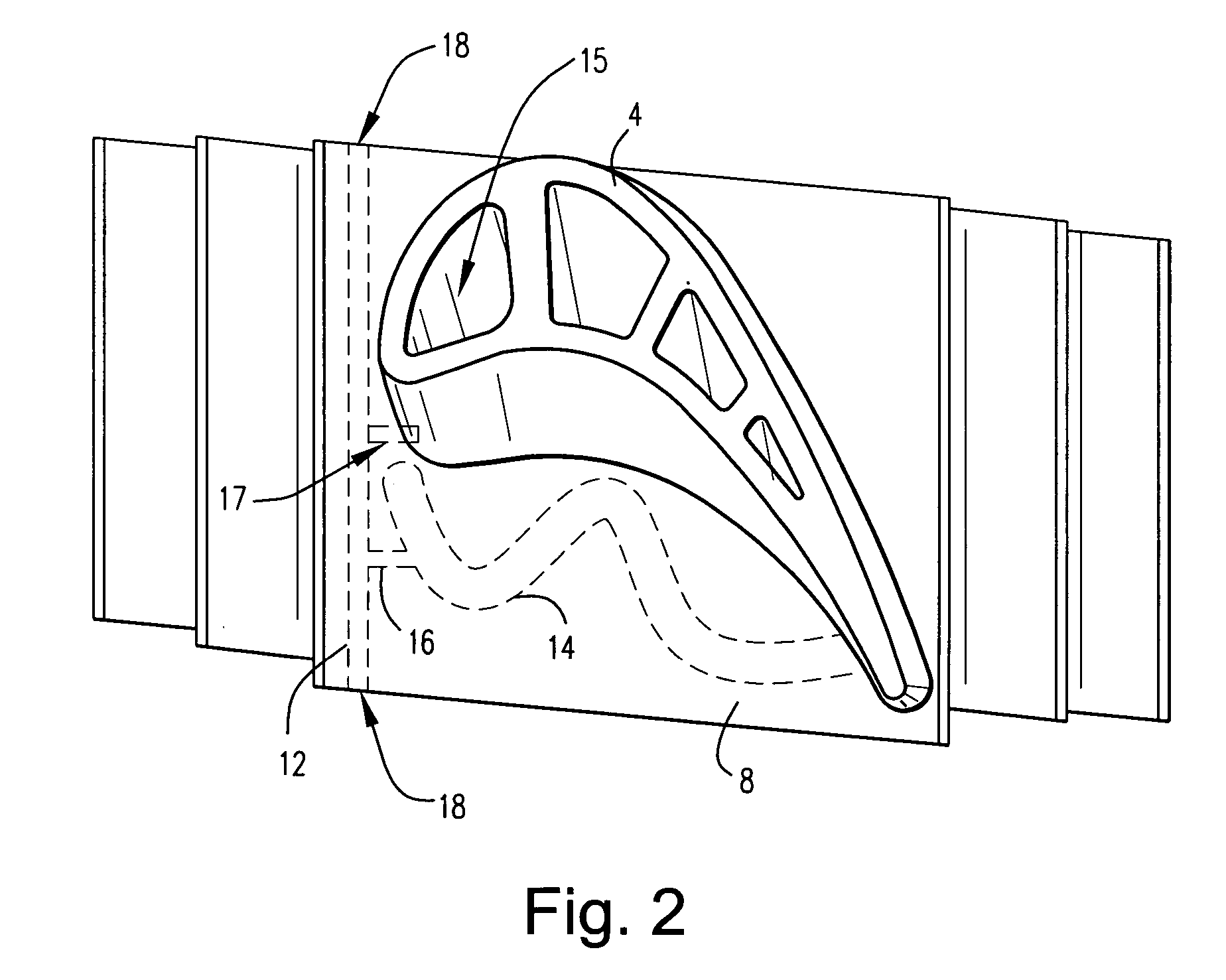
[0010] As an example embodiment, FIGS. 1 and 2 illustrate a turbine bucket 2 having an airfoil portion 4 and a root portion 6 with a substantially planar platform 8 at an interface between the airfoil portion and the root portion. A cooling media, such as cooling steam, is supplied from the bucket cooling circuit (schematically shown at 15) or platform cooling circuit (schematically shown at 14) to a forward cav...


PUM


Abstract

In a turbine bucket having an airfoil portion and a root portion with a substantially planar platform at an interface between the airfoil portion and the root portion, a platform cooling arrangement including a cavity extending along the forward portion of the platform, and at least one inlet bore extending from a source of cooling medium to the cavity, and at least one outlet opening for expelling cooling medium from the cavity.

Description

BACKGROUND OF THE INVENTION [0001] This invention relates to the cooling of turbine buckets and, specifically, to the cooling of the platform region of the bucket, at the leading edge of the bucket. BRIEF DESCRIPTION OF THE INVENTION [0002] Over the years, gas turbine firing temperatures have been increasing in order to improve turbine efficiency and output. As firing temperatures increase, bucket platforms, which in the past have been un-cooled, exhibit distress, such as oxidation, low cycle fatigue and creep. Film cooling has been used more recently to help cool the platforms, but film cooling is generally limited to the aft portions of the platform where the gas path flow has been accelerated sufficiently to drop the static pressure to a level where there is sufficient supply pressure to have positive film flow without hot gas ingestion. Platform leading edges are in a region where there is insufficient pressure to utilize film cooling but is also a region where there is distress...

Claims


Application Information

Patent Timeline
Patent Type & Authority Applications(United States)
IPC IPC(8): F01D11/00
CPCF01D5/082F01D5/187F05D2240/121F05D2240/303F05D2240/81F05D2260/202F05D2260/205
Inventor ITZEL, GARY MICHAELWEBBON, WAYLON WILLARD
Owner GENERAL ELECTRIC CO
Why Eureka
Try Eureka