Conductive endless belt

a technology of conductive and endless belts, applied in the field of conductive endless belts, can solve the problems of increasing the size and price of the apparatus, affecting the transfer efficiency, and the inability to obtain high image quality, so as to achieve less volume resistance variation and environment dependency, good image, and good durability

Inactive Publication Date: 2007-05-24
BRIDGESTONE CORP
View PDF16 Cites 21 Cited by
  • Summary
  • Abstract
  • Description
  • Claims
  • Application Information

AI Technical Summary

Benefits of technology

[0040] According to the first invention, by forming the above structure, desired performance of the belt such as elastic modulus, creep resistance, and bending durability is satisfied, while implementing a belt with less volume resistance variation and environment dependency. Therefore, an image forming apparatus using such belt of the present invention is capable of providing good image without causing problems such as poor imaging derived from elongation and deformation of the belt.
[0041] According to the second invention, by forming the above structure, a belt with various desired performance of the belt such as elastic modulus, charging characteristics as well as good durability, while satisfying desired performance in glossiness and setting performance can be implemented. Therefore, an image forming apparatus using such belt of the present invention is capable of providing good image without causing problems such as poor imaging derived from elongation and deformation of the belt

Problems solved by technology

However, controlling gradation is very difficult in this system, so there is a problem that high image quality cannot be obtained.
This system provides a good image, but four photo conductive drums, charge mechanisms and develop mechanisms for each photo conductive drum are arranged in tandem, which increasing the size as well as price of the apparatus.
However, resistance value changes depending on environmental variation, which affects transfer efficiency.
The belt tends to be affected by the thickness and width of the paper, which is also disadvantage.
Repeating transfer accumulates charge on the belt, therefore transfer electric pressure goes high, disadvantageously.
However, there is a problem that the type of the recording medium recording medium is limited, since heavy paper such as post card is hard to be rolled on the transfer drum.
However, in this case, low melting thermoplastic elastomer is used for the base resin, accordingly elastic modulus of the belt is low and creep resistance has no advantage, so that there is a problem that belt peripheral length is changed by repeat use, which causes problem in the image.
Furthermore, in the art disclosed in Japanese Published Unexamined Patent Application No. 2000-62993, elastomer polyester with low fusing point is used, therefore a similar problem in above mentioned Japanese Published Examined Patent Application No.
H8-7505 and Japanese Published Unexamined Patent Application No. 2004-272209 occurs, as well as a problem that resistance variation in belt circumferential direction is high since carbon black is used as a conductive agent.
In addition, in Japanese Published Unexamined Patent Application No. 2005-62822, thickener was added to improve dispersibility of high viscosity PBT and low viscosity elastomer polyester, which decreased residence variation, however, since carbon black was used as a conductive agent, the result was not necessarily satisfied.
On the other hand, the belt disclosed in Japanese Published Unexamined Patent Application No. 2002-132053 has high glossiness, but has a problem in belt durability due to insufficient flexibility, therefore the crystallization of resin is progressed as using under high temperature and high humidity condition, which deteriorates the setting performance.
Additionally, since the belt disclosed in Japanese Published Unexamined Patent Application No. 2000-62993 uses elastomer with low fusing point, the durability thereof is good, but the belt has problems such as offset image due to occurrence of elongation and image degrading due to deformation under high temperature and high humidity condition.

Method used


Image

  • Conductive endless belt
  • Conductive endless belt
  • Conductive endless belt

Examples


Embodiment Construction

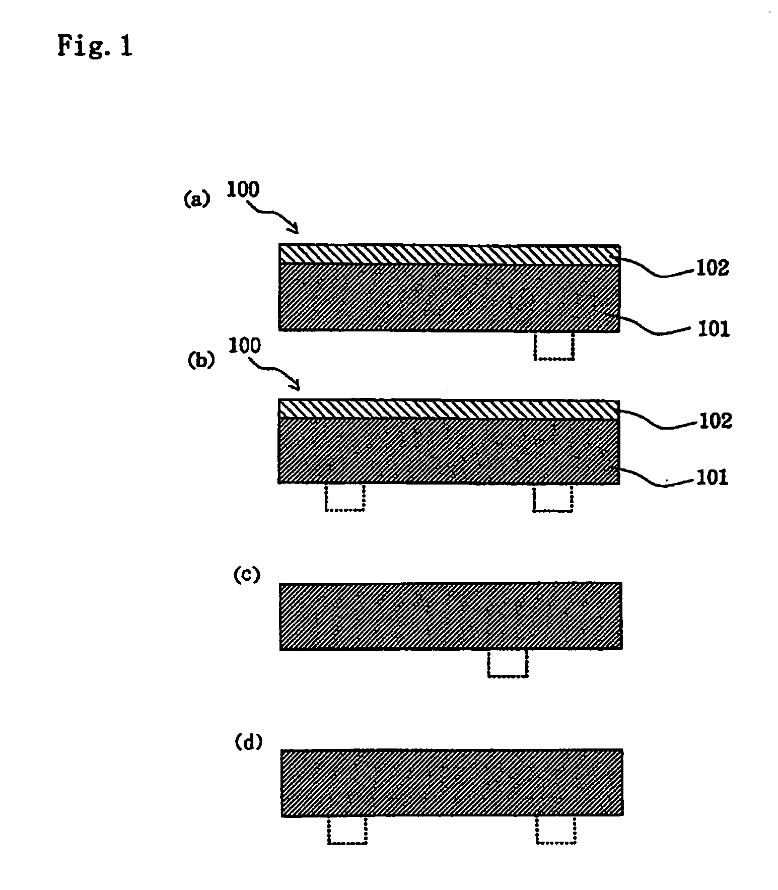
[0046] Specifically described below is a preferred embodiment of the present invention.

[0047] Conductive endless belts generally include a joint type and a Pointless type (so-called seamless belt), and either type may be used in the present invention. It is preferably a seamless belt. The conductive endless belt of the present invention can be used as a transfer member and the like of the tandem system, intermediate transfer system, and tandem intermediate transfer system as described above.

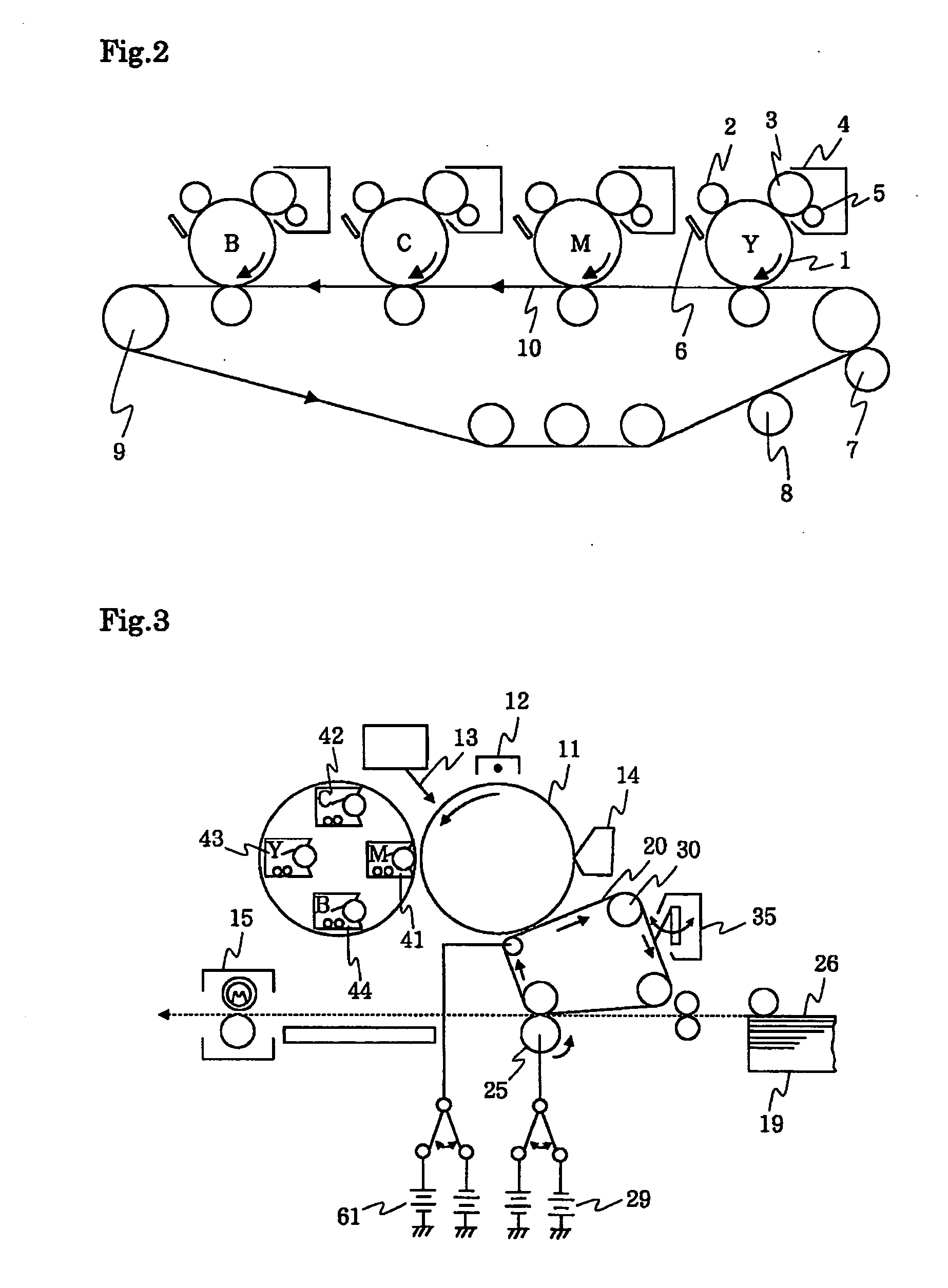
[0048] First, when the conductive endless belt of the present invention is, for example a transfer transport belt indicated by reference numeral 10 in FIG. 2, the belt is driven by a driving member such as driving roller 9, and toners are successively transferred onto a recording medium transported by the drive to form a color image.

[0049] Second, when a conductive endless belt of the present invention is, for example a intermediate transfer member indicated by reference numeral 20 in FIG. 3, ...


PUM

PropertyMeasurementUnit
crystalline melting pointaaaaaaaaaa
melting pointaaaaaaaaaa
tensile elastic modulusaaaaaaaaaa

Abstract

A conductive endless belt is composed of elastomer polyester with a crystalline melting point at 210° C. or more, or mainly composed of the elastomer polyester, and a thermoplastic polyester-based resin at 49 wt % or less, added a polymer ion conductive agent and a carbon black. The conductive endless belt. satisfies elastic modulus, creep resistance, bending durability, etc. and has decreased volume resistance variation and environment dependency while having superior durability, glossiness and setting performance that satisfying desired performance, without causing problems such as offset image.

Description

FIELD OF THE INVENTION [0001] This invention relates to a conductive endless belt (hereinafter simply refer to as “belt”) used for transferring toner image on recording medium such as paper, in the electrostatic recording process in electrophotographic machines such as copying machine and printer, and electrostatic recording machines, latent image carrier, etc. carrying electrostatic latent image on surface thereof that is formed by supplying developer to the surface of image forming body, and an image forming apparatus using it. BACKGROUND OF THE INVENTION [0002] Conventionally, in the electrostatic recording process of copying machine, printer, etc., the following print method is employed. First, by uniformly charging the surface of a photo conductor (latent image carrier), then projecting an image from an optical system, and removing charge from a part where is projected the light, an electrostatic latent image is formed. Then, by supplying toner with this electrostatic latent im...

Claims


Application Information

Patent Timeline
Patent Type & Authority Applications(United States)
IPC IPC(8): B32B27/36B32B27/00
CPCC08K3/04C08L67/025C08L77/12G03G15/0131G03G15/1605C08L2666/20G03G15/162Y10T428/31786Y10T428/31504Y10T428/13Y10T428/1352Y10T428/1386Y10T428/139
Inventor SUZUKI, TAKAHIROOSAKI, TOSHIYUKIMACHIDA, KUNIONISHIMURO, YOICHI
Owner BRIDGESTONE CORP
Why Eureka
Try Eureka