
Implant fixation methods and apparatus

a technology of fixation methods and implants, applied in the field of implant fixation methods and apparatuses, can solve problems such as loss of stability, changes in various bones, discs, joints and ligaments of the body, and chronic back pain

Inactive Publication Date: 2007-05-24
DEPUY SPINE INC (US)
View PDF55 Cites 111 Cited by
  • Summary
  • Abstract
  • Description
  • Claims
  • Application Information

AI Technical Summary

Benefits of technology

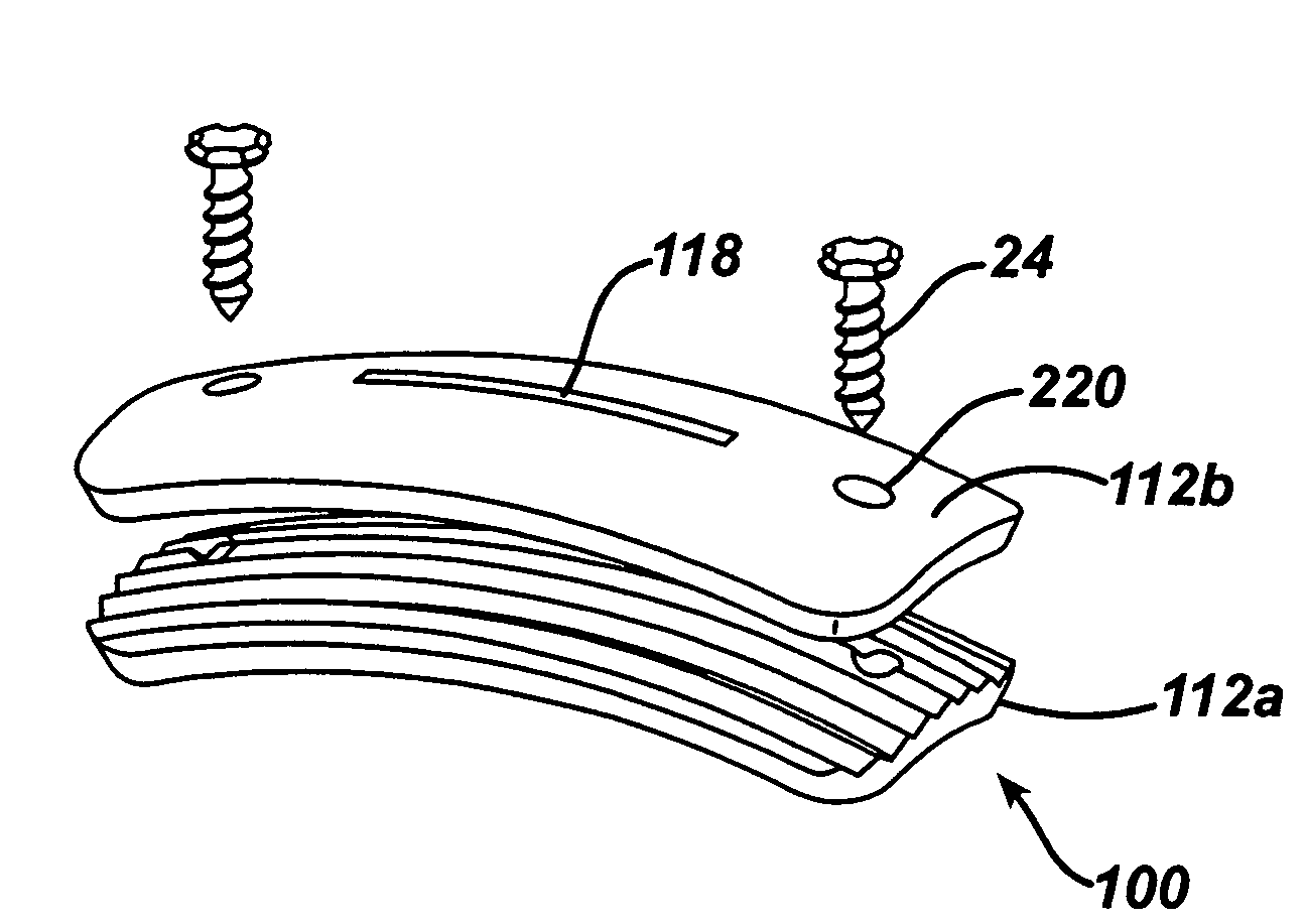
[0012] In another embodiment described herein a method of implanting a soft tissue implant is provided. The method can include the step of providing a first plate body having an upper surface and a lower implant contacting surface and a second plate body having an upper implant contacting surface and a lower tissue contacting surface. An implant can be positioned between the first and second plate bodies and / or between the second plate body and a native tissue surface. Fixing the first and second plates to a hard tissue surface can fix the implant between the first and second plate bodies and between the second plate body and a native tissue surface.

Problems solved by technology

Disease, advancing age, and trauma can lead to changes in various bones, discs, joints, and ligaments of the body.
This condition often results in chronic back pain, which can be anywhere from mild to severe.
This can cause a loss of stability, particular where a mobility retaining prosthesis is utilized.
One drawback of such procedures is that the tissue implant can be weakened by the fixation procedure.
When the screw, tack, or staple is driven through the implant it creates a weak spot, which may tear under load.
Another drawback of conventional fixation techniques is that the fixation devices hold only a minimal portion of the implant in contact with the native tissue surface.

Method used


Image

  • Implant fixation methods and apparatus
  • Implant fixation methods and apparatus
  • Implant fixation methods and apparatus

Examples


Embodiment Construction

[0058] Certain exemplary embodiments will now be described to provide an overall understanding of the principles of the structure, function, manufacture, and use of the devices and methods disclosed herein. One or more examples of these embodiments are illustrated in the accompanying drawings. Those skilled in the art will understand that the devices and methods specifically described herein and illustrated in the accompanying drawings are non-limiting exemplary embodiments and that the scope of the present invention is defined solely by the claims. The features illustrated or described in connection with one exemplary embodiment may be combined with the features of other embodiments. Such modifications and variations are intended to be included within the scope of the present invention

[0059] Various exemplary methods and devices are provided for fixing an implant to native tissue, such as, bone. One such device includes at least one plate having a body with an upper surface and a ...


PUM


Abstract

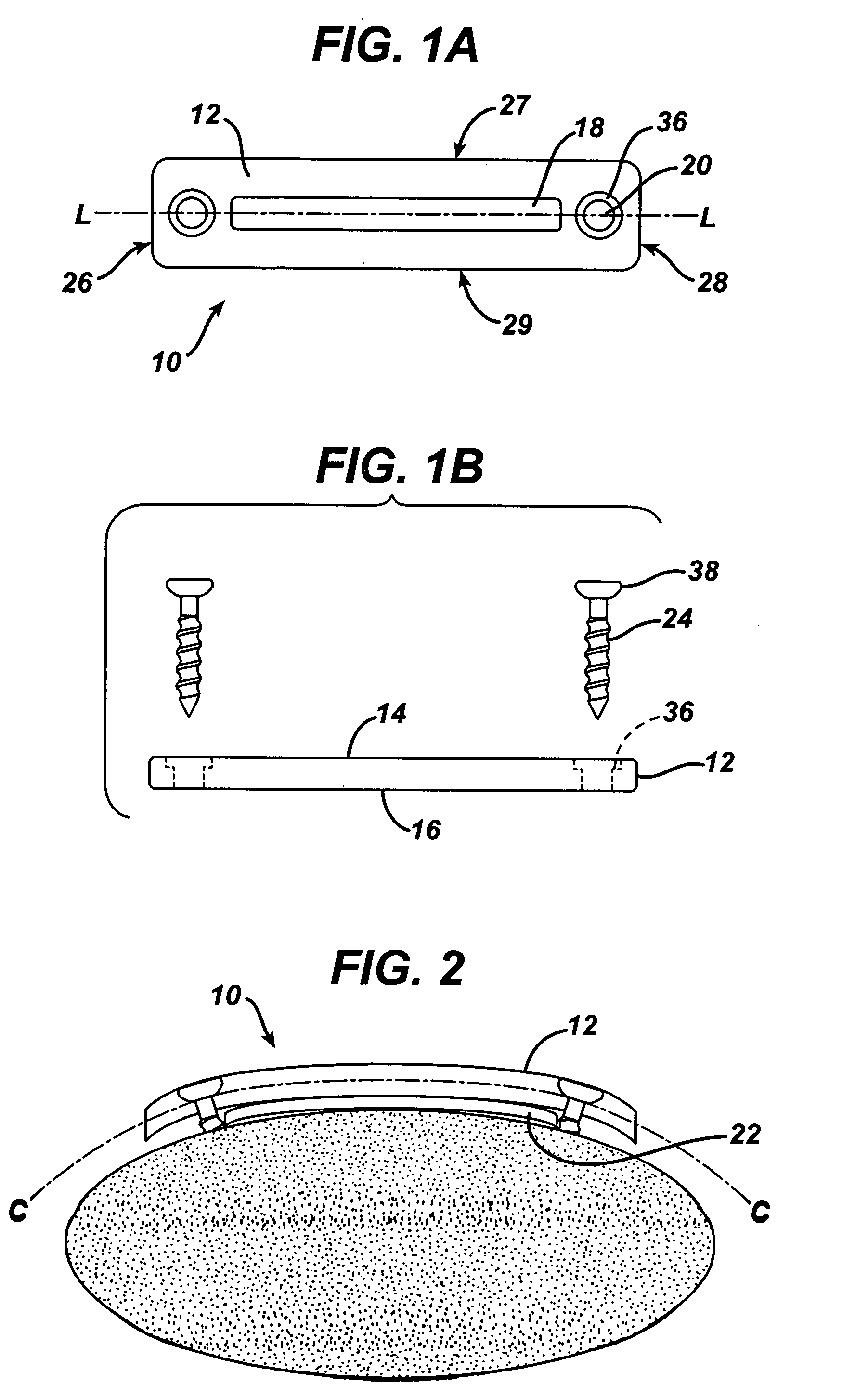
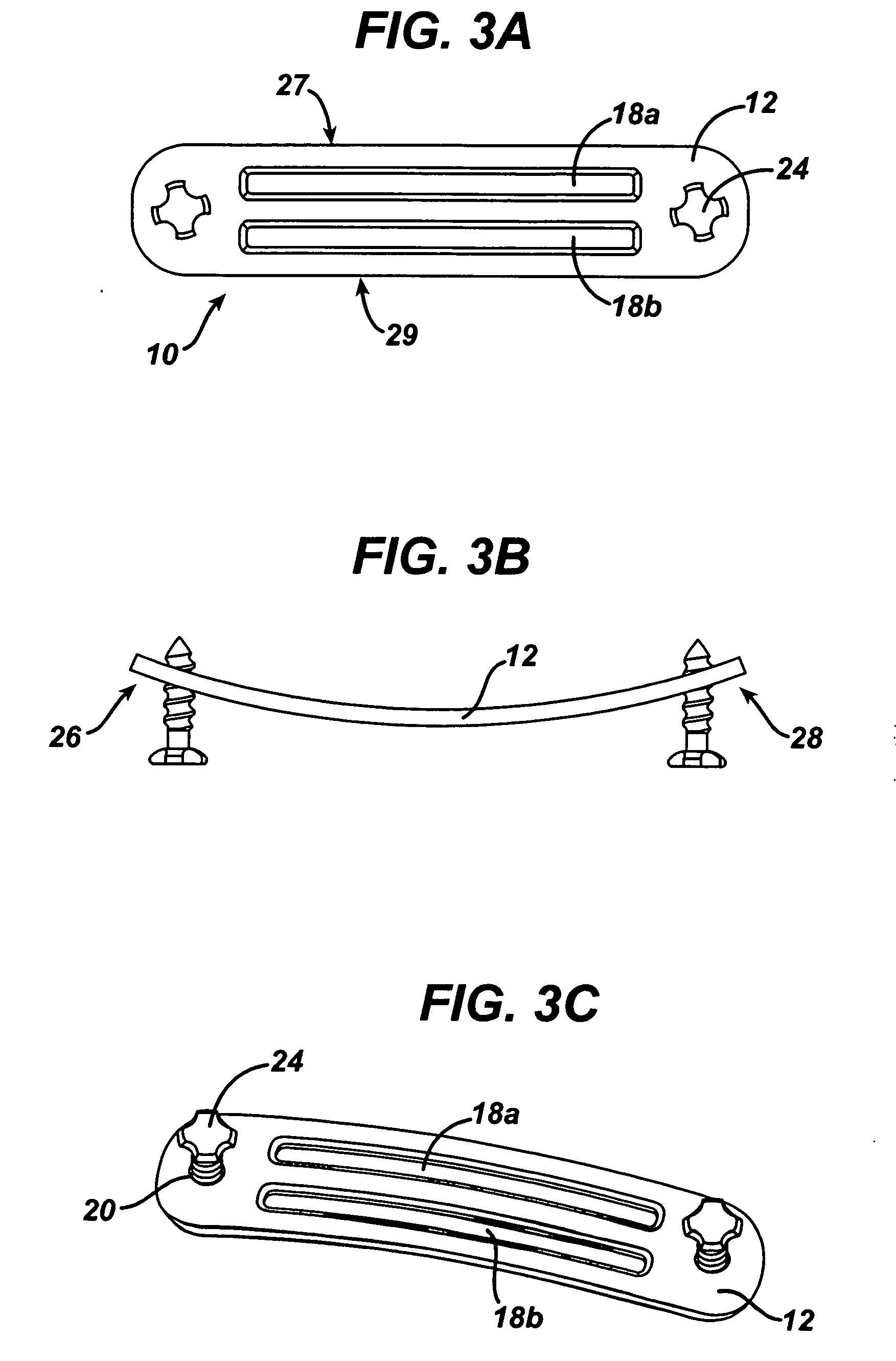
Various exemplary methods and devices are provided for fixing an implant to native tissue, such as, bone. The devices can include first and second plate bodies, each having an upper surface and a lower tissue contacting surface. The bodies can provides a large contact area for fixing the tissue implant to bone, such that the implant can be securely held in position without requiring penetration of the implant. In one embodiment, the plate bodies can include at least one aperture for receiving a fixation device and a tissue implant receiving opening through which a tissue implant can be threaded prior to fixing the plate bodies to bone.

Description

BACKGROUND OF THE INVENTION [0001] Disease, advancing age, and trauma can lead to changes in various bones, discs, joints, and ligaments of the body. Some changes and trauma often manifest themselves in the form of damage or degeneration to a spinal disc. This condition often results in chronic back pain, which can be anywhere from mild to severe. This pain can sometimes be eliminated by removing the disc tissue between adjacent vertebral bodies and replacing it with a prosthetic device. [0002] One type of procedure is spinal fusion, in which two adjacent vertebral bodies are jointed together after removing the intervening intervertebral disc. A prosthetic device is usually placed between the two adjacent vertebral bodies, in place of the removed disc, to fill the space left by the removed disc and to allow bone to grow between the two vertebral bodies. Alternatively, proposals have been made to replace the defective disc with an artificial disc that preserves the natural mobility b...

Claims


Application Information

Patent Timeline
IPC IPC(8): A61B17/80A61B17/84
CPCA61F2/0811A61F2002/0829A61F2002/0858A61F2002/0864A61F2002/0888
Inventor FRASER, ROBERTKHANZADA, REHANO'NEIL, MICHAEL J.
Owner DEPUY SPINE INC (US)
Learn More