Utility knife

Active Publication Date: 2007-05-31
MARTOR
View PDF13 Cites 21 Cited by
  • Summary
  • Abstract
  • Description
  • Claims
  • Application Information

AI Technical Summary

Benefits of technology

[0013] The advantage of the invention is that manufacturing expenses are significantly reduced because it is no longer required to make separate, mirror-reversed knives for right- and left-handed users. Furthermore, another longitudinal slot with operating projection for the blade holder is no longer required on the second knife housing side. On knives with the additional longitudinal slot, greater amounts of contaminants may penetrate into the knife housing and impair functioning of the knife. Furthermore, it is no longer necessary to produce knives with varying blade extension lengths. The knife according to the invention allows the blade extension length to be adjusted. Once set, the user can push out the blade without paying attention as it is only the maximum extension that is limited
[0014] Furthermore, the knife according to the invention ensures more comfortable manipulation than knives with operating projections on both sides. In the case of knives with operating projections on both sides, movement of the additional operating projection may be impaired by the palm enclosing the knife housing. Furthermore, the additional operating projection as well as the additional longitudinal slot may prevent the user from firmly gripping the knife. The knife according to the invention overcomes these disadvantages and can still be handled by right-handed and left-handed users alike. In addition, the knife according to the present invention offers greater design freedom regarding the shape of the knife, since an additional operating projection limits the design freedom of the knife.
[0015] According to a first embodiment, the stop device comprises a stop element that

Problems solved by technology

On knives with the additional longitudinal slot, greater amounts of contaminants may penetrate into the knife housing and impair functioning of the knife.
In the

Method used


Image

  • Utility knife
  • Utility knife
  • Utility knife

Examples


Example

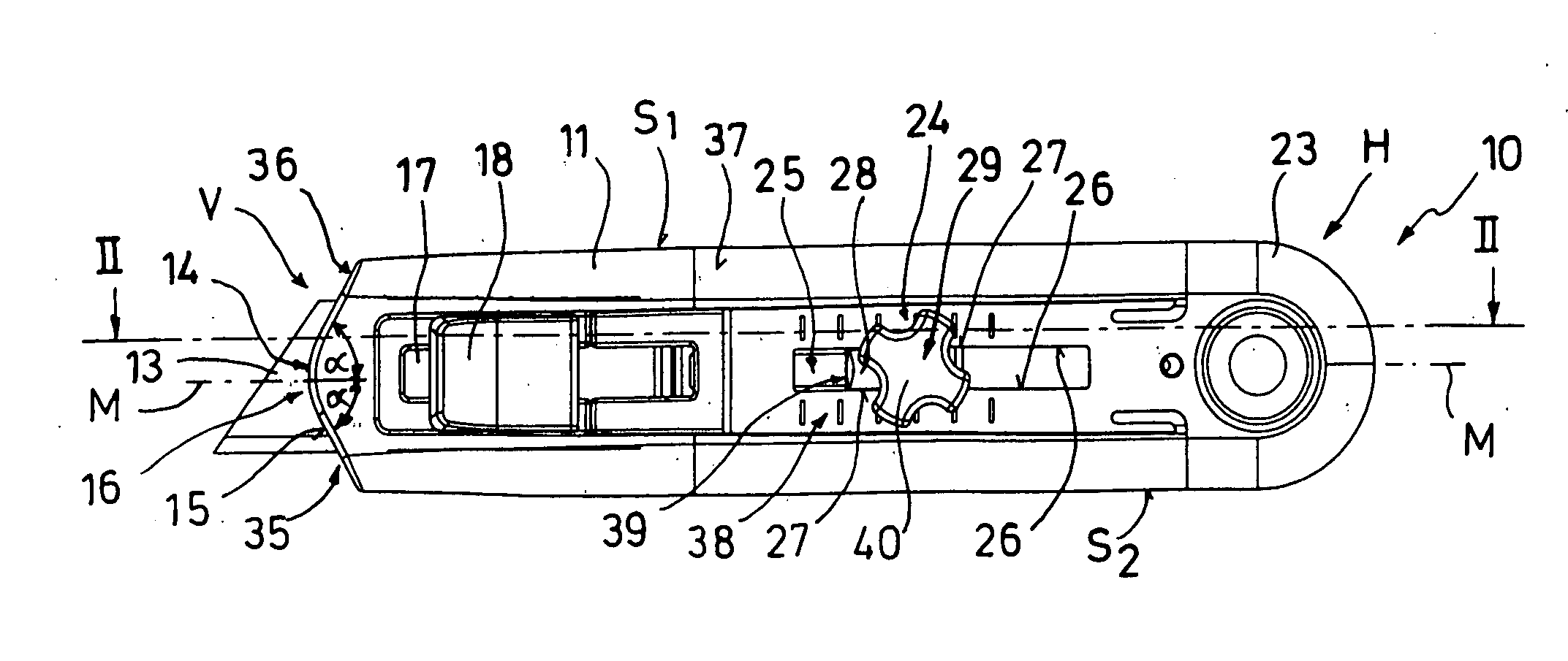
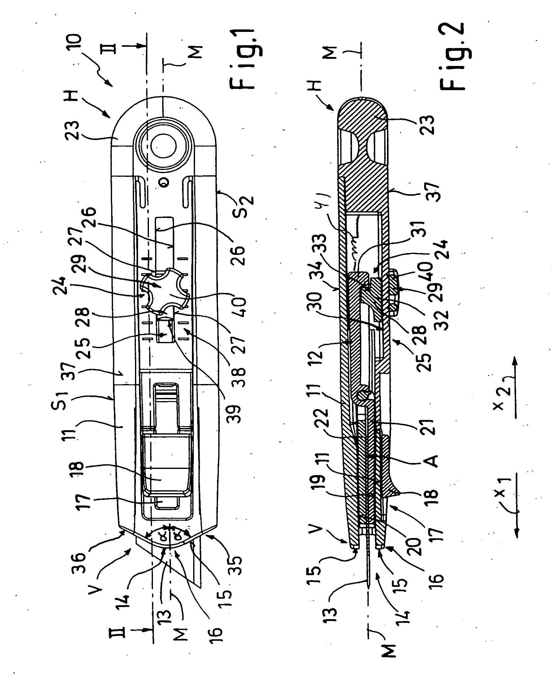
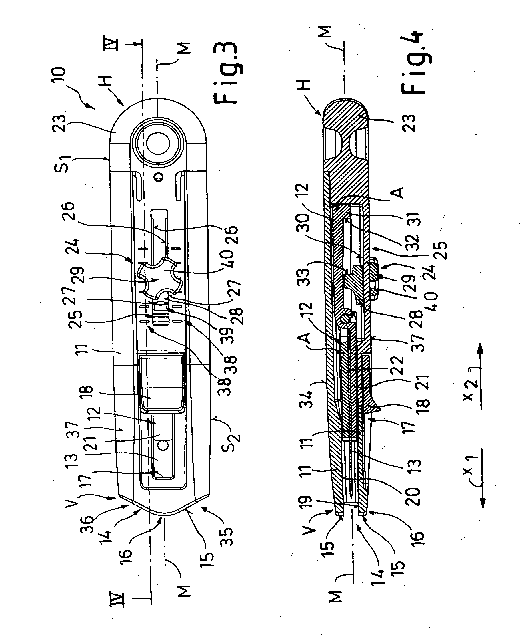
[0032] As seen in the drawing, a knife 10 has a housing 11 has well as a blade 13 that is fitted to a blade holder 12. A front end V of the housing 11 is formed with a hole 14 from which the blade 13 can extend. The hole 14 opens at a front edge 15 that is directed longitudinally forward relative to a longitudinal axis M of the knife housing 11 and forms a front central point or tip 16 of the knife housing 11. Toward narrow longitudinally extending knife edges S1 and S2 the housing front edge 15 is angled back toward he direction of the rear knife end H at an obtuse angle α to the longitudinal axis M as a pair of flat flanks 35 and 36.

[0033] The knife housing 11 is provided with a longitudinal slot 17 on a flat knife housing face 37, in which slot an operating projection 18 for the blade holder 12 is guided. The blade holder 12 is slidable in a guide A of the knife housing 11, so that the holder 12 can be displaced between a non-usage rear position shown in FIG. 2 and a front cutti...


PUM


Abstract

A utility knife for use with a replaceable flat blade has an elongated housing having a V-shaped front end formed by a pair of flat flanks extending at an obtuse angle to each other and meeting at a central point. The housing further has a longitudinally and longitudinally extending guide open at the front end, a longitudinally extending and transversely open slot, and a longitudinally extending holding face directed transversely opposite to the slot. A blade holder having a seat for the blade is slidable in the housing between a front use position with the blade projecting longitudinally forwardly from the guide past the front end and a rear storage position with the blade wholly contained in the housing rearward of the front end. An actuator connected to the holder and exposed at the slot is accessible from outside the housing and operable to shift the blade in the holder between the front and rear positions.

Description

FIELD OF THE INVENTION [0001] The present invention relates to a utility knife. More particularly this invention concerns such a knife with a replaceable and retractable blade. BACKGROUND OF THE INVENTION [0002] A standard utility knife for use with a replaceable flat razor blade has as described in U.S. Pat. No. 4,320,576 an elongated housing having a front end, a longitudinally and longitudinally extending guide open at the front end, a longitudinally extending and transversely open slot, and a longitudinally forwardly directed holding face directed transversely opposite to the slot. A blade holder having a seat for the blade is slidable in the housing between a front use position with the blade projecting longitudinally forward from the guide at the front end and a rear storage position with the blade wholly contained in the housing rearward of the front end. An actuator connected to the holder and exposed at the slot is accessible from outside the housing and operable to shift t...

Claims


Application Information

Patent Timeline
IPC IPC(8): B26B1/08
CPCB26B5/001B26B5/003
Inventor POLEI, GUDULA
Owner MARTOR
Why Eureka
Try Eureka