Precast panel mounting system

a technology for mounting brackets and prefabricated panels, which is applied in the direction of building components, ceramic shaping apparatus, structural elements, etc., can solve the problems of affecting the overall durability and value of the building, and the leakage at the roof-to-wall junction, etc., to achieve uniform air space and facilitate the placement of mounting brackets. , the effect of convenient us

Inactive Publication Date: 2007-05-31
KUELKER PETER
View PDF12 Cites 23 Cited by
  • Summary
  • Abstract
  • Description
  • Claims
  • Application Information

AI Technical Summary

Benefits of technology

[0030] In a third aspect, the invention is a forming system that facilitates accurate placement of mounting brackets in precast panels to ensure the creation of a substantially uniform air space behind the panels after they are mounted on a supporting structure.

Problems solved by technology

Although caulking or other sealant materials are typically used to seal the spaces between cladding panels, the possibility of moisture infiltration behind the cladding—as a result of vapour migration, direct penetration of rainwater (due to sealant deterioration or other factors), or leakage at roof-to-wall junctures—cannot be entirely eliminated.
If such moisture is not removed from the building envelope fairly promptly, it will tend to migrate further into the building, potentially causing a variety of problems that could entail costly maintenance and repairs and could detract from the building's overall durability and value.
Such problems may include drywall damage due to moisture absorption, rot and mold in wooden construction components (e.g., studs and sheathing), corrosion of non-rust-resistant construction hardware, and staining on interior building finishes.
The essential problem facing designers of cladding panel support systems is to provide hangers or brackets that can adequately support weight of the panels at a distance away from the face of the supporting structure (i.e., so as to provide the desired air space), without significantly impeding the passage of water or water vapour through the air space.
It is readily apparent that cladding panels using vertical hangers of this general type cannot be effectively used on unsheathed walls unless the hangers coincide with stud locations, or unless horizontal strapping is installed across the studs at specific vertical intervals (and at additional cost) to receive the hanger fasteners.
However, none of these prior art systems addresses all of the problems and desirable features discussed above.
Moreover, these systems are primarily intended for use in the construction of curtain wall systems or mounting large, heavy concrete cladding panels on large buildings, and are not conveniently adaptable for use with comparatively small and light concrete cladding panels for residential housing structures.

Method used


Image

  • Precast panel mounting system
  • Precast panel mounting system
  • Precast panel mounting system

Examples


first embodiment

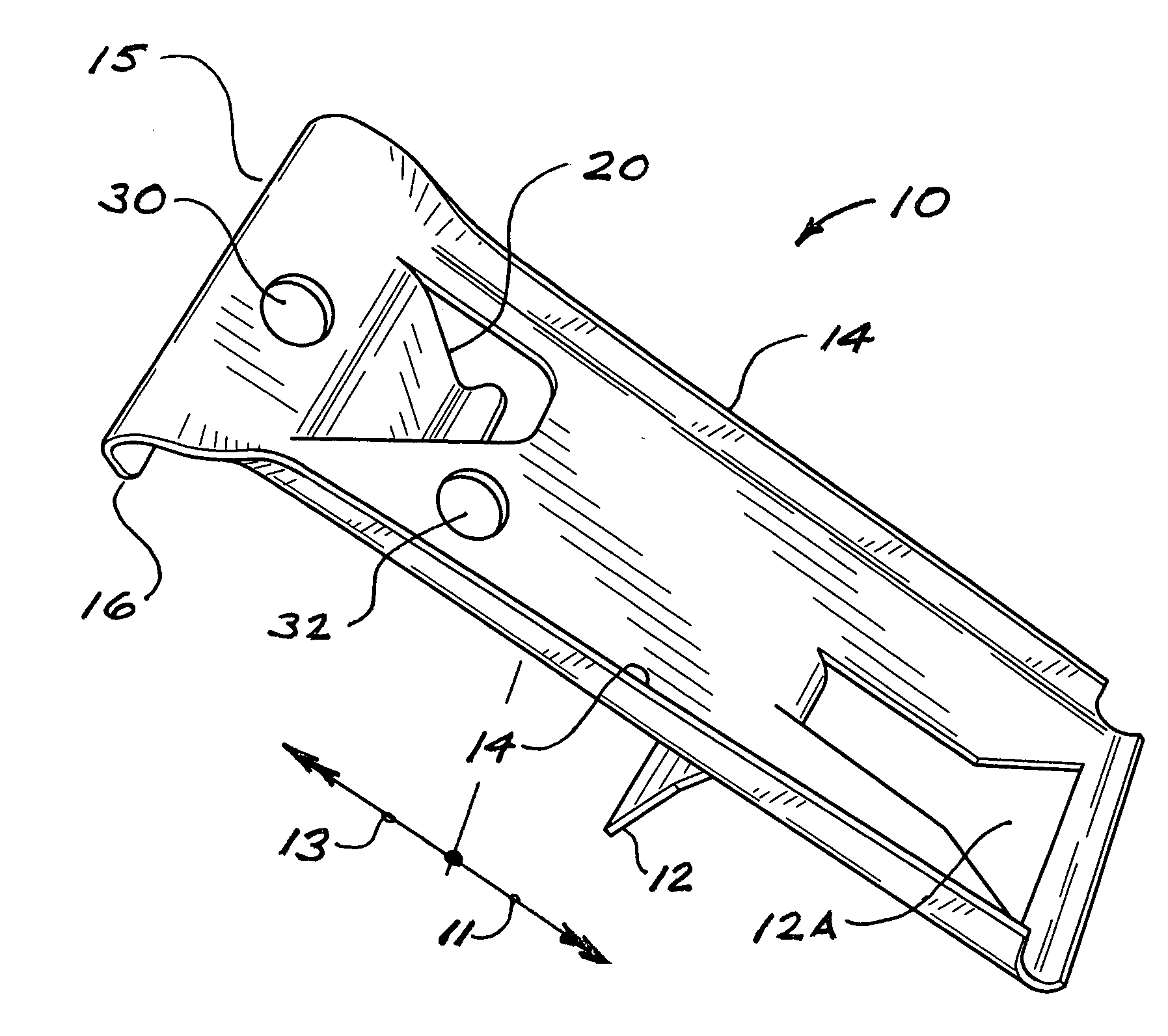
[0053] Referring to FIG. 1, a rigid, elongate mounting bracket 10 in accordance with the invention has an embedment portion 11 and a contiguous extension portion 13. The point of demarcation between embedment portion 11 and extension portion 13 is not precisely defined, but will coincide with the rear face of a precast cladding panel in which bracket 10 is embedded, as will be described in detail herein. Bracket 10 is preferably fashioned from a corrosion-resistant metal, such as stainless steel, galvanized steel, or plated steel, but other materials may also be used provided they have suitable physical properties. Persons skilled in the art will appreciate that bracket 10 could be fashioned in accordance with any of several known fabrication methods. In the preferred embodiment shown in FIG. 1, however, bracket 10 is cold-formed from sheet stock. Bracket 10 will preferably be formed with side edge flanges 14 for increased stiffness, but these are not essential to the invention.

[005...

second embodiment

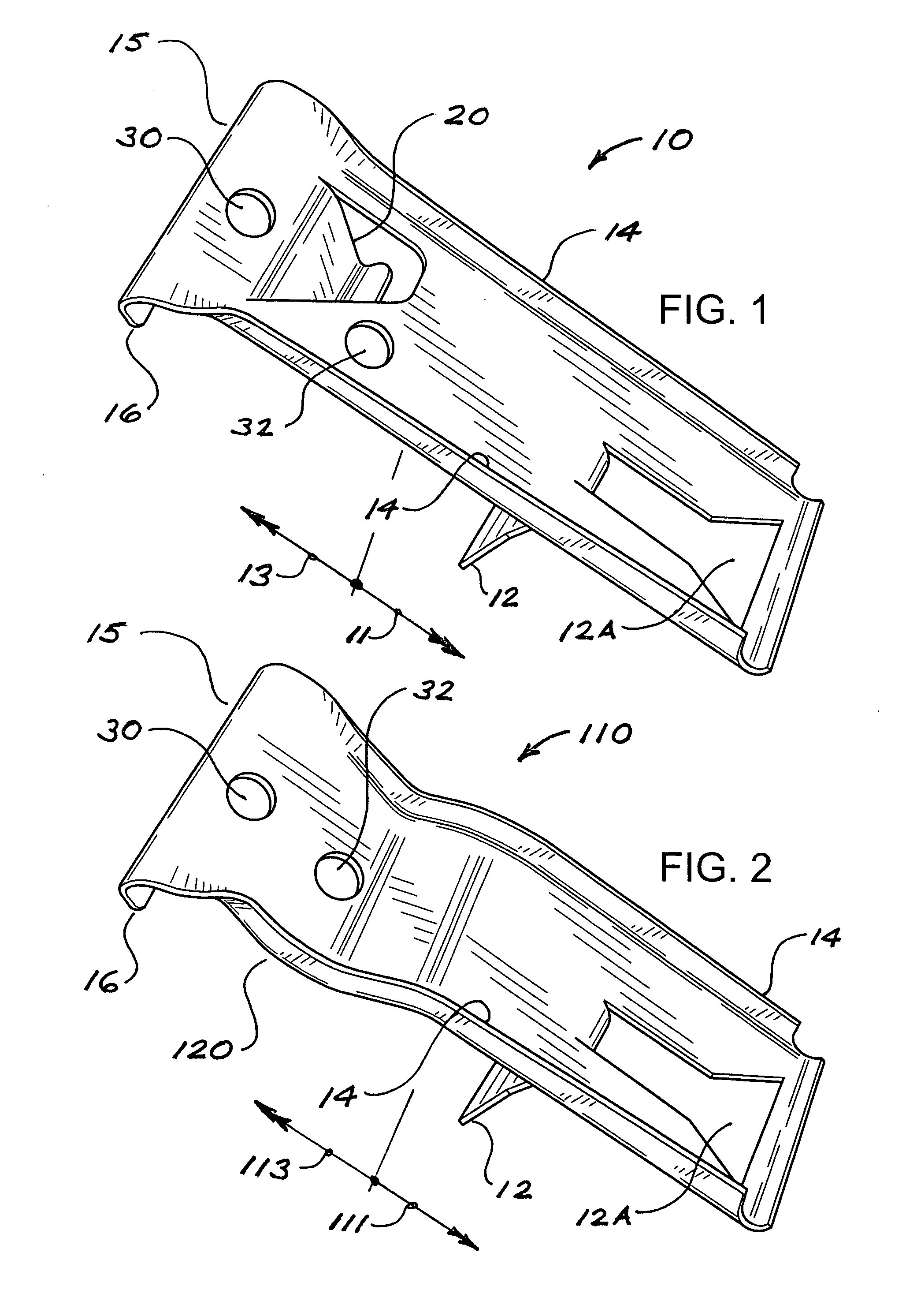
[0057]FIG. 2 illustrates a mounting bracket 110 in accordance with a Bracket 110 has several features in common with bracket 10, as indicated by the use of common reference numerals. What distinguishes bracket 110, however, is that the abutment means is provided as a shoulder 120 formed integrally with bracket 110. For greater clarity in differentiating bracket 110 from bracket 10, the embedment portion and extension portion of bracket 110 are indicated by reference numerals 111 and 113 respectively, with shoulder 120 forming part of extension portion 113.

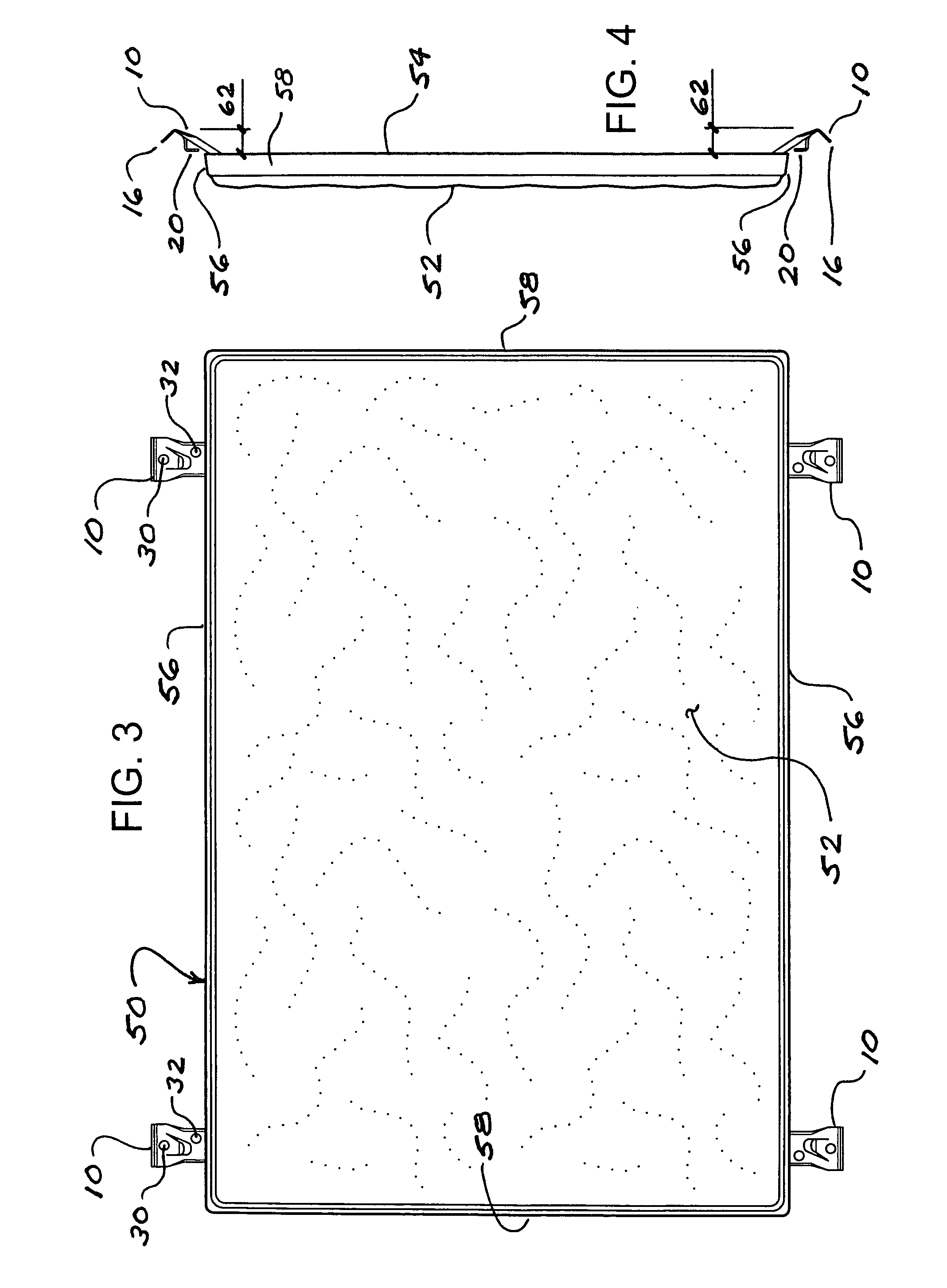
[0058]FIG. 3 is an elevation of a typical precast cladding panel 50 formed with mounting brackets 10 in accordance with the present invention; FIG. 4 is an end view (or side view) of the panel of FIG. 3. As illustrated, panel 50 has a front face 52 (which may be flat or textured as desired), a generally planar rear face 54, two longitudinal edges 56 (which may be upper or lower edges, depending on the orientation of panel 50), and...

third embodiment

[0088]FIGS. 16 and 17 illustrate the mounting bracket of the present invention. As shown in FIG. 16, alternative bracket 210 is formed from metal wire of a gauge suitable to provide the structural strength and stiffness required for specific panel applications. Bracket 210 has embedment portion 211 and extension portion 213 analogous to embedment portion 11 and extension portion 13 of the previously-described bracket 10. Bracket 210 is twist-formed to create a fastener opening 30 analogous to that of bracket 10, and to form abutment means in the form of a shoulder 220 analogous to shoulder 120 of alternative bracket 110.


PUM

PropertyMeasurementUnit
thicknessaaaaaaaaaa
thicknessaaaaaaaaaa
thicknessaaaaaaaaaa

Abstract

A rigid elongate mounting bracket has an embedment portion and an extension portion. The extension portion has a fastener opening and abutment means. When cast into a precast panel in an appropriate angular orientation adjacent to an edge of a cladding panel, the extension portion projects rearwardly and laterally away from the rear face of the panel end such that the end of the extension portion is disposed at a distance away from the panel's rear face corresponding to a desired air space, and the abutment means is substantially aligned with the panel's rear face. Each panel preferably has at least two brackets spaced along its upper edge and two more along its lower edge. A first panel may be mounted to a supporting structure using fasteners driven through the fastener openings of the upper brackets. A second panel may then be positioned with its lower brackets extending downward behind the first panel, with the abutment means of the second panel's lower brackets engaging the rear face of the first panel, such that the lower end of the second panel is laterally stabilized by the first panel, with a uniform air space being formed between the supporting structure and the panels' rear faces.

Description

FIELD OF THE INVENTION [0001] The present invention relates to precast cladding panels mounted to supporting structures, and relates in particular to mounting brackets cast into precast panels. BACKGROUND OF THE INVENTION [0002] Precast panels of various sizes and shapes are widely used as cladding on building walls, serving as components of building envelope systems intended to prevent infiltration of rain and outside air into the building. Precast cladding panels are commonly made of concrete, but may also be made with other cast materials known in the construction field. Concrete cladding panels are common on large structures such as office buildings, but they are also used on residential housing structures as an alternative to traditional cladding materials such as wood siding and brick. [0003] Whether installed on large or small buildings, it is desirable for cladding panels to be mounted in such a way that there will be a continuous air space between the rear (i.e., inner) fac...

Claims


Application Information

Patent Timeline
Patent Type & Authority Applications(United States)
IPC IPC(8): E04C3/16
CPCB28B7/24B28B23/005B28B23/0056E04F13/0816E04F13/0835
Inventor KUELKER, PETER
Owner KUELKER PETER
Why Eureka
Try Eureka