Three-dimensional display device

a display device and three-dimensional technology, applied in the field of three-dimensional display devices, can solve the problems of difficult uniformity of time-sharing type three-dimensional display devices, no more than half as fine as that of two-dimensional images, etc., and achieve the effect of uniform light transmittance ra

Inactive Publication Date: 2007-05-31
SAMSUNG DISPLAY CO LTD
View PDF2 Cites 10 Cited by
  • Summary
  • Abstract
  • Description
  • Claims
  • Application Information

AI Technical Summary

Benefits of technology

[0018] It is an aspect of the present invention to provide a three-dimensional display device that can maintain a uniform light transmittance rate at portions corresponding to electrodes of the device during operation of the device.

Problems solved by technology

However, since the left and right images are entered into the respective eyes of the user, the resolution of a three-dimensional image is no more than half as fine as that of a two-dimensional image.
However, it is difficult for the time-sharing type of three-dimensional display device to maintain a uniform light transmittance rate due to differing lengths of electrode paths along which applied voltages are conducted.

Method used


Image

  • Three-dimensional display device
  • Three-dimensional display device
  • Three-dimensional display device

Examples


experimental example

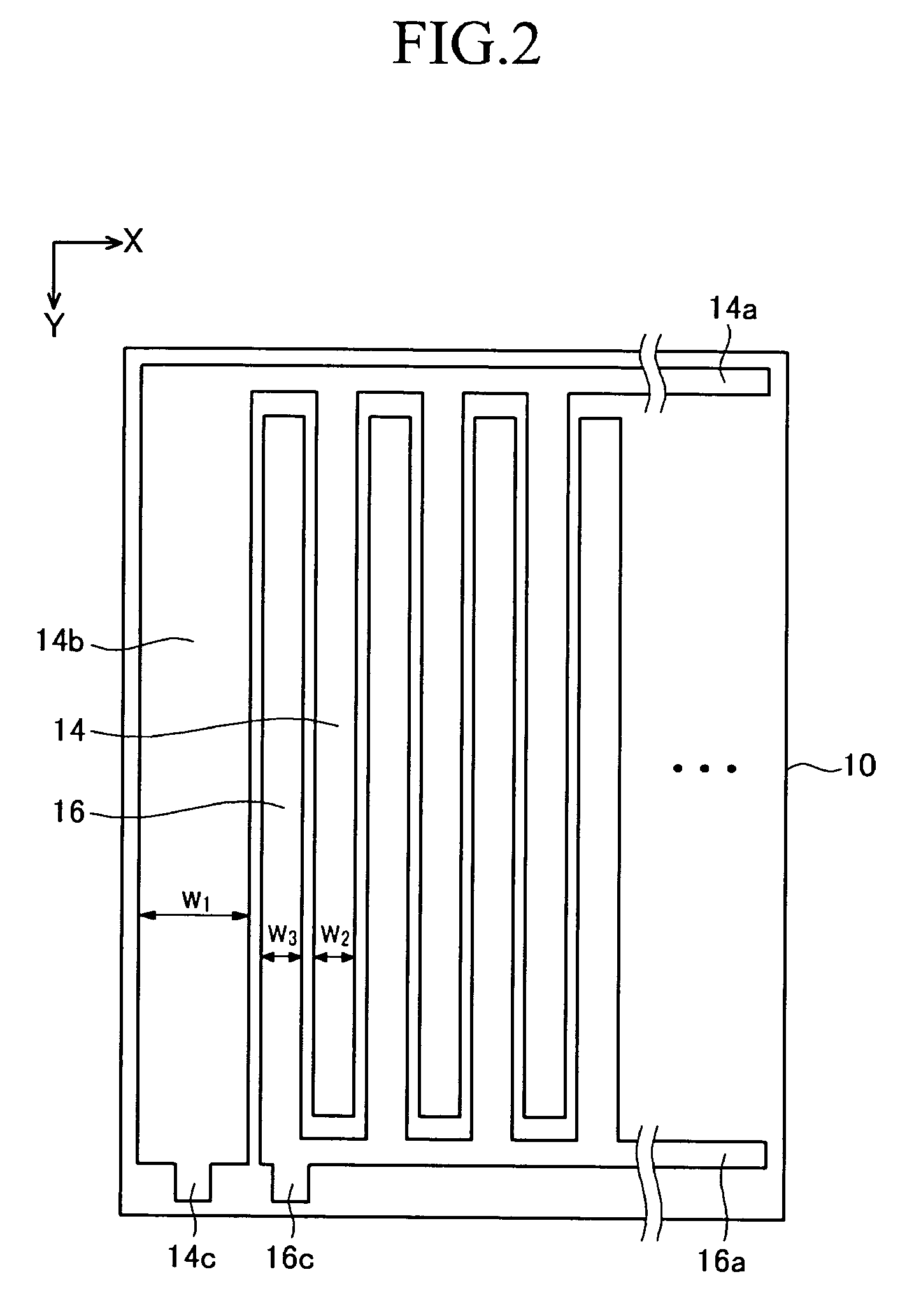
[0138] A first terminal electrode was formed with a material used to form a first electrode and a second electrode. Also, the width of the first terminal electrode was configured to be 3.396 times greater than the respective widths of the first electrode and the second electrode.

[0139] An auxiliary connection electrode similar to that described in the fourth exemplary embodiment was formed at an end of a second connection electrode such that a path having an increased electrical resistance was made.

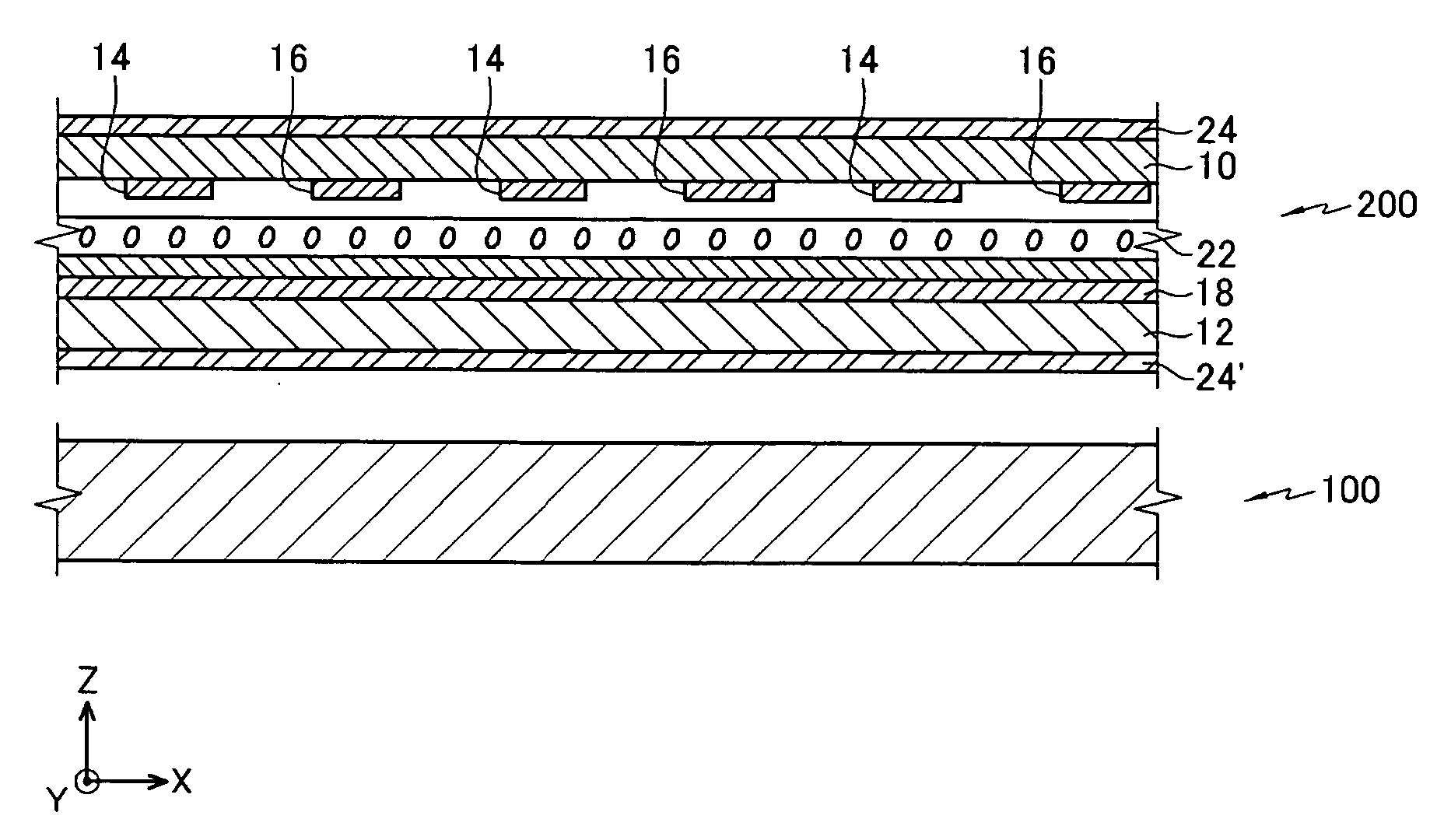
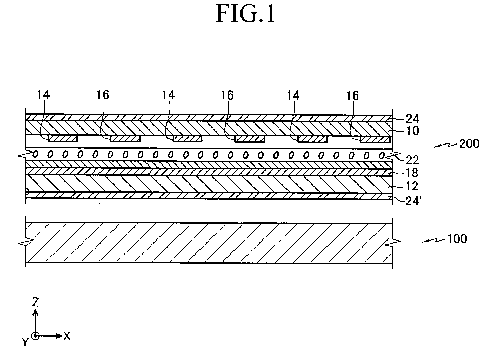
[0140] Also, relative transmission brightness according to the sampling time was measured. The first electrode and the second electrode were formed with ITO and had equal widths.


PUM

PropertyMeasurementUnit
voltageaaaaaaaaaa
electric resistanceaaaaaaaaaa
electric resistancesaaaaaaaaaa

Abstract

A three-dimensional display device includes an image display portion displaying left and right eye images, and a parallax barrier directing the left and right eye images respectively towards left and right eyes of a user. The parallax barrier includes first electrodes located on a first substrate, a first connection electrode electrically connecting the first electrodes, a first terminal electrode connected to an end of the first connection electrode, a first connection terminal connected to the first terminal electrode, second electrodes located between the first electrodes, a second connection electrode electrically connecting the second electrodes, a second connection terminal connected to an end of the second connection electrode, a common electrode located on a second substrate facing the first substrate, and a liquid crystal layer disposed between the first and second substrates. The first terminal electrode has a lower electric resistance than the first electrodes and the second electrodes.

Description

CROSS-REFERENCE TO RELATED APPLICATION [0001] This application claims priority to and the benefit of Korean Patent Application No. 10-2005-0115586 filed in the Korean Intellectual Property Office on Nov. 30, 2005, the entire content of which is incorporated herein by reference. BACKGROUND OF THE INVENTION [0002] 1. Field of the Invention [0003] The present invention relates to a three-dimensional display device, and in particular, to an autostereoscopic three-dimensional display device using a parallax barrier. [0004] 2. Description of the Related Art [0005] A three-dimensional display device may be categorized as a stereoscopic display device where a user wears viewing aids such as polarizing glasses, or an autostereoscopic display device where the user can see a desired three-dimensional image without wearing such viewing aids. [0006] A common autostereoscopic display device utilizes an optical separation element, such as a lenticular lens, a parallax barrier, or a microlens array...

Claims


Application Information

Patent Timeline
Patent Type & Authority Applications(United States)
IPC IPC(8): G09G3/28G02B27/22G02F1/13G03B35/24H04N13/04
CPCG02F1/134309H04N13/0413H04N13/0452H04N13/0409H04N13/356H04N13/31H04N13/315
Inventor LEE, HYO-JINLEE, JANG-DOOJANG, HYOUNG-WOOKNAM, HUIKIM, BEOM-SHIKSONG, MYOUNG-SEOPKU, JA-SEUNG
Owner SAMSUNG DISPLAY CO LTD
Why Eureka
Try Eureka