
Generation of motion blur

a motion blur and motion technology, applied in the field of motion blur generation, can solve the problems of increasing frame rate, visual artifacts, and small frame to frame displacement, and achieve the effect of less aliasing, acceptable motion blur, and acceptable motion blur

Inactive Publication Date: 2007-05-31
NXP BV
View PDF3 Cites 20 Cited by
  • Summary
  • Abstract
  • Description
  • Claims
  • Application Information

AI Technical Summary

Benefits of technology

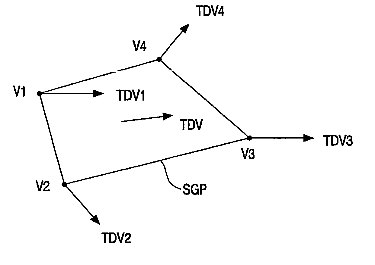
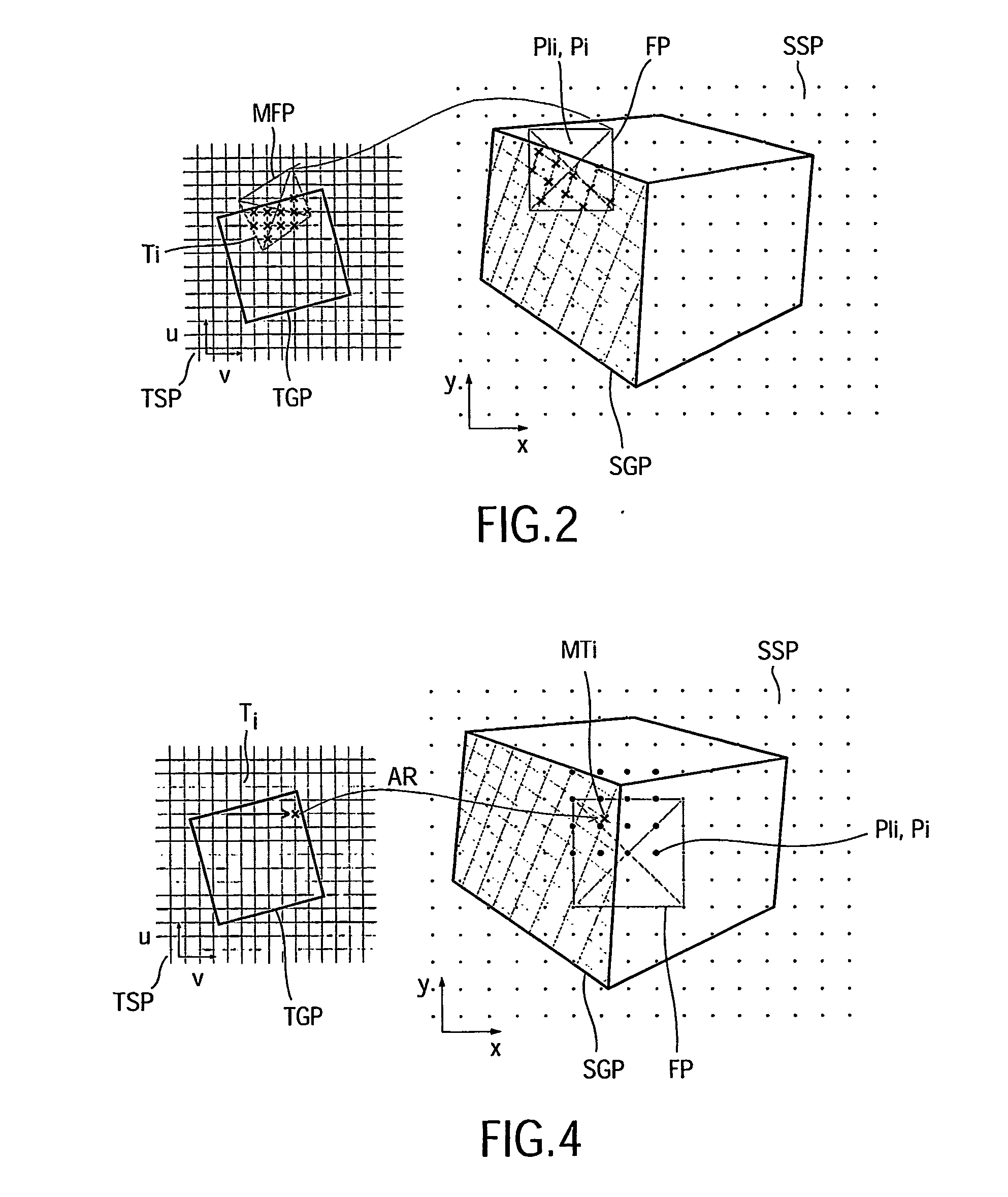
[0009] In the method of generating motion blur in a graphics system in accordance with the first aspect of the invention, geometrical information defining a shape of a graphics primitive is received, this geometrical information may be the three-dimensional graphics data referred to in U.S. Pat. No. 6,426,755. It is also possible to use two-dimensional graphics data which is supplied by an application in a system which has less processing recourses. The method uses displacement information determining a displacement vector defining a direction of motion of the graphics primitive to sample the graphics primitive in the direction of the motion to obtain input samples. A one dimensional spatial filtering of the input samples provides the temporal filtering. In this manner a high quality blur is obtained without requiring complex processing and filtering.
[0028] In an embodiment in accordance with the invention as defined in claim 12, the distance over which the resampled pixels or the resampled texels are distributed is rounded to a multiple of the distance between resampled texels. This avoids a doubling of the number of resampled texels during the accumulation of the distributed intensities of the texels.

Problems solved by technology

The large displacement may lead to visual artifacts, often referred to as temporal aliasing.
An expensive approach to alleviate temporal aliasing is to increase the frame rate such that the motions of the objects result in smaller frame to frame displacements.
However, a high refresh rate requires an expensive display apparatus capable to display images with these high refresh rates.
This approach provides an approximation of motion blur only, it does not provide a satisfactory quality of the images.

Method used


Image

  • Generation of motion blur
  • Generation of motion blur
  • Generation of motion blur

Examples


Embodiment Construction

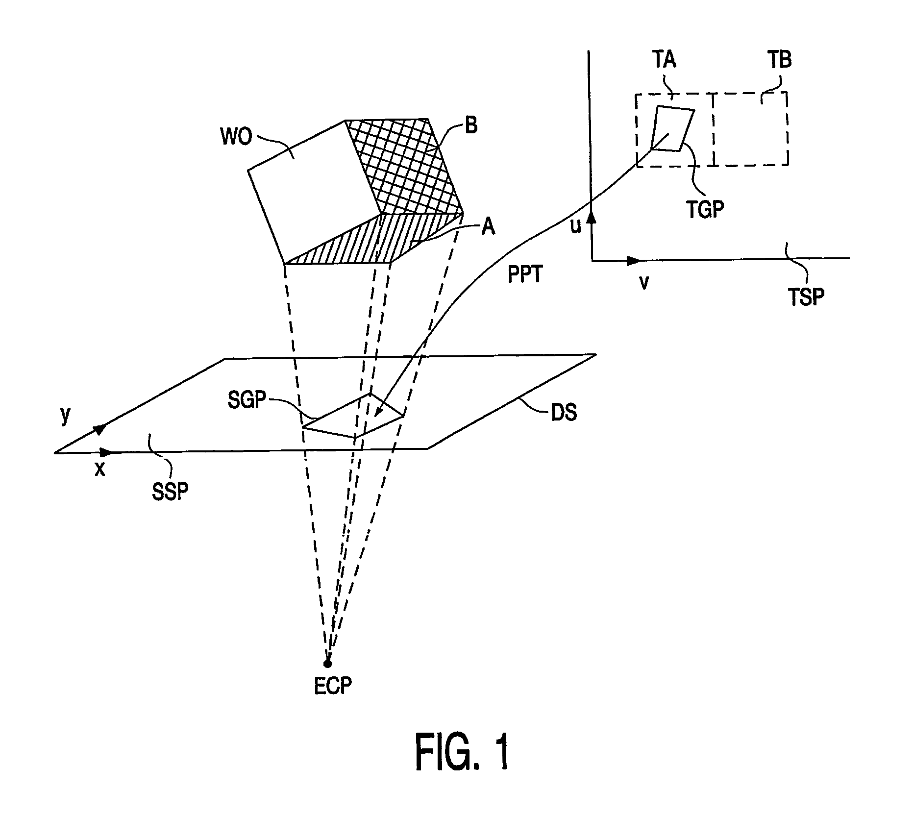
[0050]FIG. 1 elucidates a display of a real world 3D object on a display screen. A real world object WO, which may be a three-dimensional object such as the cube shown, is projected on a two-dimensional display screen DS. The three-dimensional object WO has a surface structure or texture which defines the appearance of the three-dimensional object WO. In FIG. 1 the polygon A has a texture TA and the polygon B has a texture TB. The polygons A and B are with a more general term also referred to as the real world graphics primitives.

[0051] The projection of the real world object WO is obtained by defining an eye or camera position ECP with respect to the screen DS. In FIG. 1 is shown how the polygon SGP corresponding to the polygon A is projected on the screen DS. The polygon SGP in the screen space SSP defined by the coordinates X and Y is also referred to as a graphics primitive instead of the graphics primitive in the screen space. Thus, with graphics primitive is indicated the pol...


PUM


Abstract

In a method of generating motion blur in a 3D-graphics system, geometrical information (GI) defining a shape of a graphics primitive (GP) is received (RSS; RTS) from a 3D-application. A displacement vector (SDV; TDV) defining a direction of motion of the graphics primitive (GP) is also received from the 3D-application or is determined from the geometrical information. The graphics primitive (GP) is sampled (RSS; RTS) in the direction indicated by the displacement vector to obtain input samples (RPi), and an one dimensional spatial filtering (ODF) is performed on the input samples (RPi) to obtain temporal prefiltering.

Description

FIELD OF THE INVENTION [0001] The invention relates to a method of generating motion blur in a graphics system, and to a graphics computer system. BACKGROUND OF THE INVENTION [0002] Usually, images are displayed on a display screen of a display apparatus in successive frames of lines. 3D objects displayed on the display screen which move with a large speed have a large frame to frame displacement. This is in particular the case for 3D games. The large displacement may lead to visual artifacts, often referred to as temporal aliasing. Temporal filtering, which adds blur to the images, alleviates these artifacts. [0003] An expensive approach to alleviate temporal aliasing is to increase the frame rate such that the motions of the objects result in smaller frame to frame displacements. However, a high refresh rate requires an expensive display apparatus capable to display images with these high refresh rates. [0004] Another approach is temporal super-sampling wherein the images are rend...

Claims


Application Information

Patent Timeline
Patent Type & Authority Applications(United States)
IPC IPC(8): G06T15/70G06T13/20
CPCG06T13/20
Inventor MEINDS, KORNELIS
Owner NXP BV
Learn More