Image capturing apparatus, image sensor, and image processing method

a technology of image processing and image capture, which is applied in the direction of picture signal generators, television system scanning details, television systems, etc., can solve the problems of affecting the image quality of fine objects, so as to reduce the deterioration of image quality

Inactive Publication Date: 2006-11-02
CANON KK
View PDF9 Cites 19 Cited by
  • Summary
  • Abstract
  • Description
  • Claims
  • Application Information

AI Technical Summary

Benefits of technology

[0011] The present invention has been made in consideration of the above problems and has as its first object to reduce a deterioration in image quality after thinning operation when pixels are read out upon thinning.
[0012] It is a second object of the present invention to reduce aliasing which occurs after thinning operation.
[0013] It is a third object of the present invention to reduce jaggies which are produced after thinning operation.

Problems solved by technology

This results in the occurrence of jaggies (a stair-step pattern) on a fine object image.
If, therefore, the size of an output image increases, a great deterioration in image quality may occur.
As a consequence, jaggies appear on an oblique line or the like, resulting in a great deterioration in image quality.

Method used


Image

  • Image capturing apparatus, image sensor, and image processing method
  • Image capturing apparatus, image sensor, and image processing method
  • Image capturing apparatus, image sensor, and image processing method

Examples


first embodiment

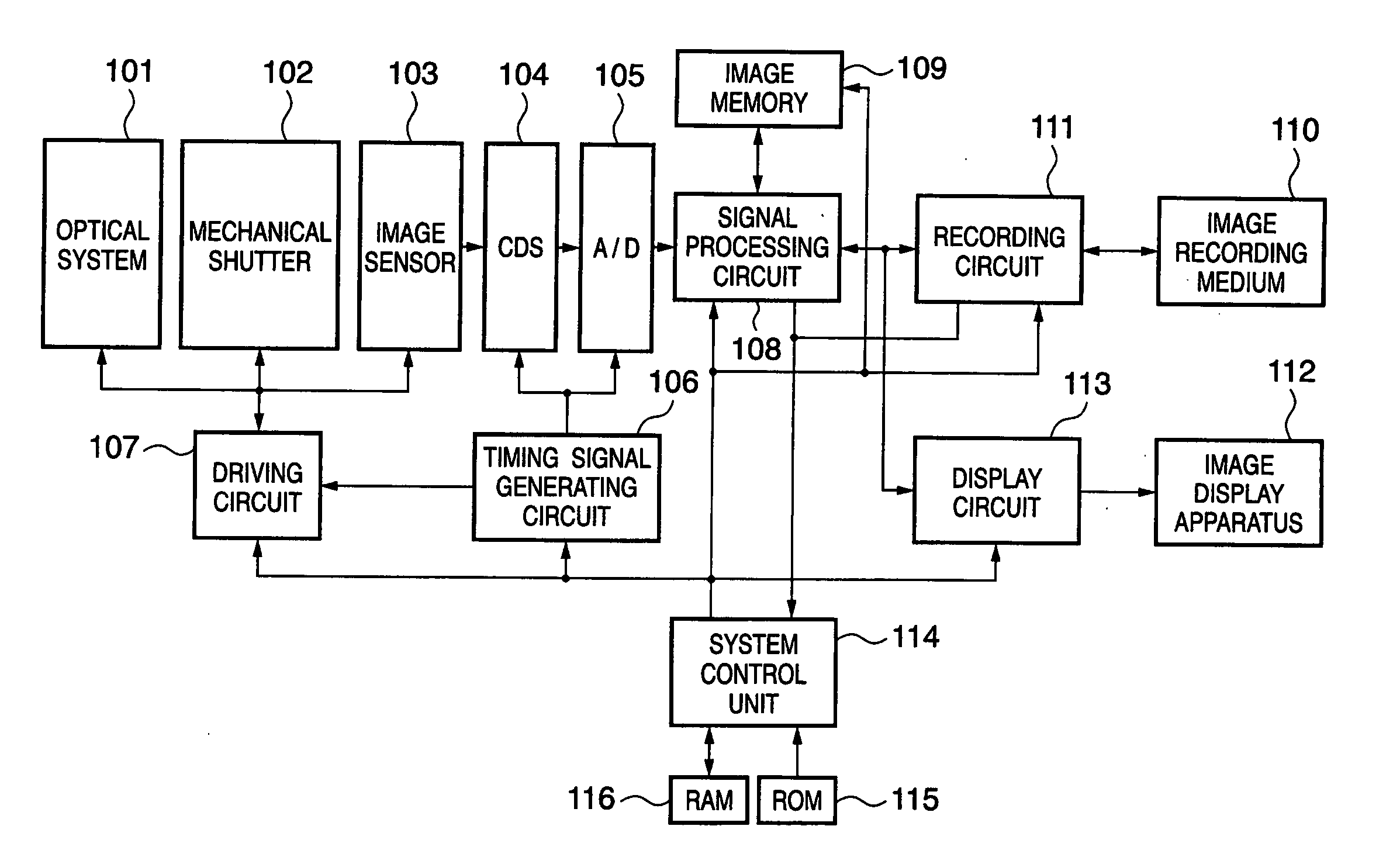
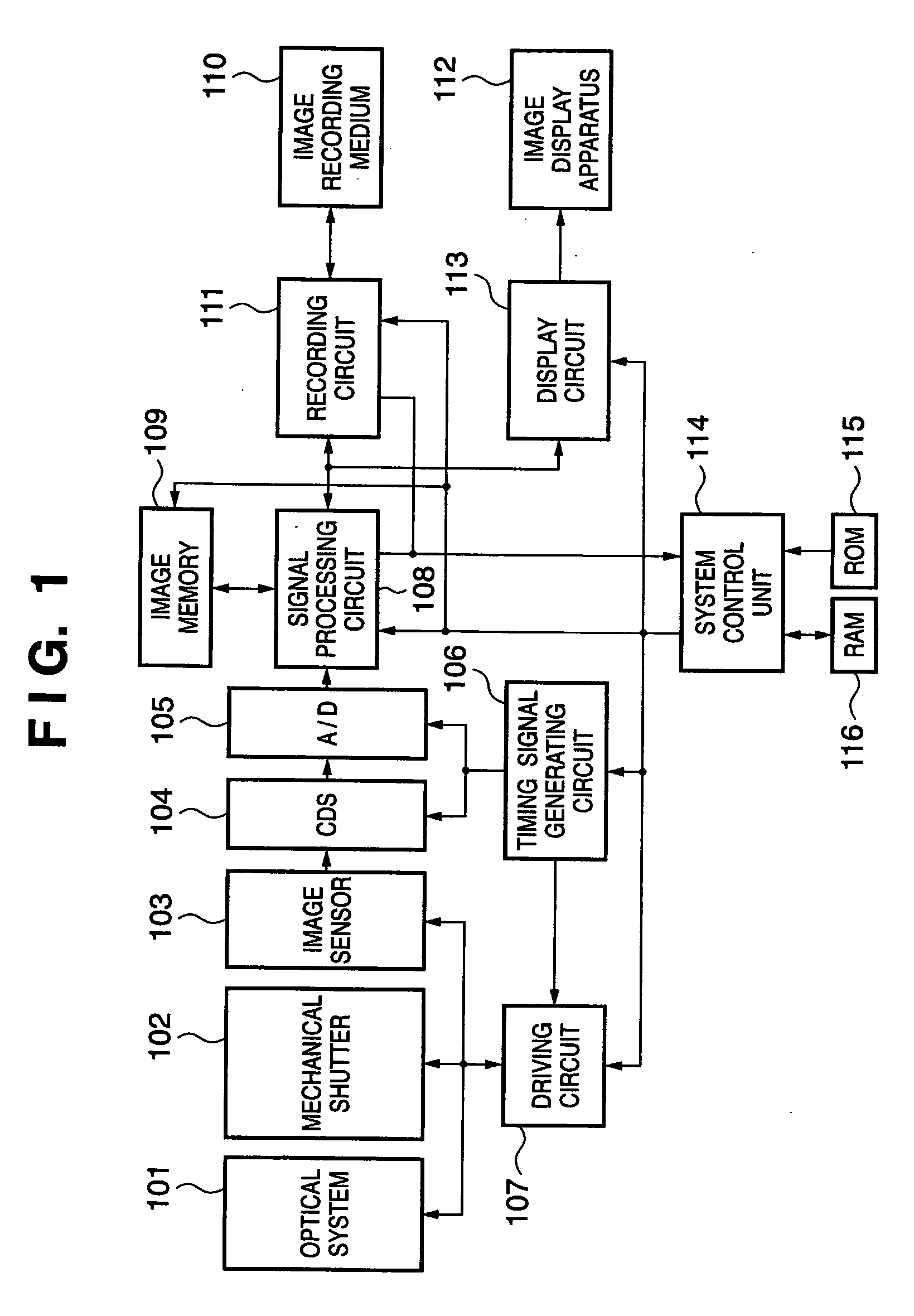
[0031] An example of the hardware arrangement of an image capturing apparatus according to this embodiment will be described first with reference to FIG. 1.

[0032] Reference numeral 101 denotes an optical system comprising a lens and a stop; 102, a mechanical shutter; and 103, an image sensor. The image sensor 103 in this embodiment includes a color filter having a primary color Bayer pattern. Reference numeral 104 denotes a CDS circuit which performs analog signal processing; and 105, an A / D converter which converts an analog signal into a digital signal.

[0033] Reference numeral 106 denotes a timing signal generating circuit which generates signals for operating the image sensor 103, the CDS circuit 104, and the A / D converter 105; 107, a driving circuit for the optical system 101, mechanical shutter 102, and image sensor 103; 108, a signal processing circuit which performs signal processing necessary for captured image data; and 109, an image memory which stores image data having ...

second embodiment

[0078] The second embodiment of the present invention will be described next. This embodiment performs adding processing in the sensor vertical direction in addition to adding processing in the sensor horizontal direction in the first embodiment, thereby preventing a deterioration in image quality due to thinning processing in the vertical direction. As described above, this embodiment differs from the first embodiment in that adding processing is performed in the sensor vertical direction, but other arrangements are the same. The same reference numerals in FIGS. 1 to 7 as in the first embodiment denote the same portions in the second embodiment, and a detailed description thereof will be omitted.

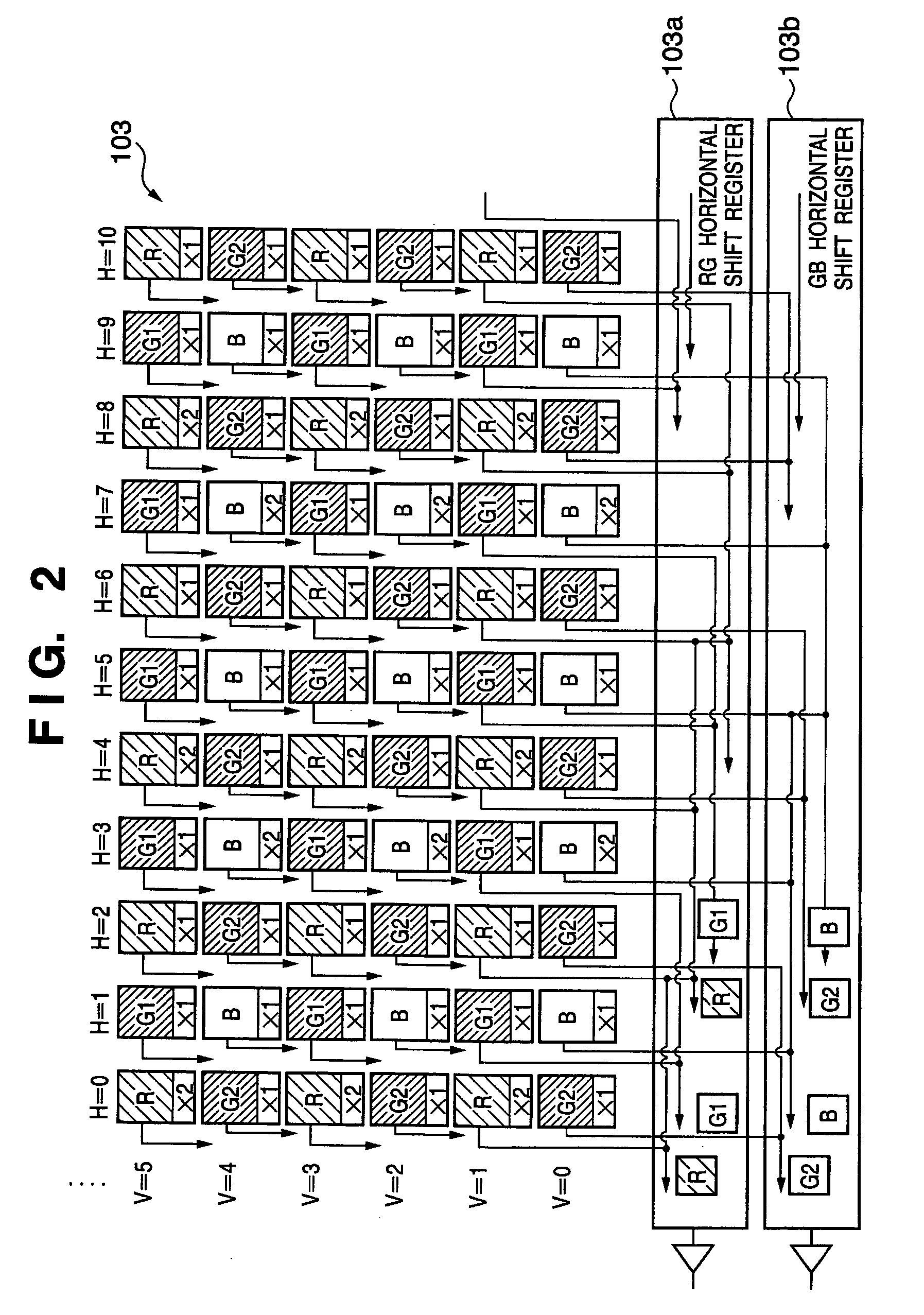
[0079] In an image sensor 103, circuit arrangements for adding processing in the horizontal direction, of circuit arrangements for applying different gains for each pixel and circuit arrangements for pixel addition, are the same as those in the first embodiment. Since it is obvious that ad...

third embodiment

[0087] The third embodiment of the present invention will be described next. This embodiment is characterized in that after gains having a common pattern are applied to pixels of each color first and the pixels of the same colors are added and averaged in a horizontal shift register to obtain a low-pass filter effect, the pixels are thinned and read out. This embodiment is also characterized in that the period of a gain applied to pixels of the same color is changed in accordance with a thinning ratio. Other arrangements are the same as those in the first and second embodiments. Therefore, the same reference numerals in FIGS. 1 to 8 as in the first and second embodiments described above denote the same portions in the third embodiment, and a detailed description thereof will be omitted.

[0088]FIG. 9 is a view conceptually showing an example of a method of reading out pixels upon thinning them to ⅓ in the horizontal direction in the addition mode in an image sensor according to this ...


PUM


Abstract

This invention is directed to reduce a deterioration in image quality after thinning operation when pixels are read out upon thinning. An image sensor is designed such that different gains are applied on a pixel basis. After periodical gains are applied to the respective pixels, the pixels of the same colors are added and averaged to obtain a low-pass filter effect before thinning processing for the pixels in the sensor, thereby preventing the occurrence of aliasing (moiré) due to thinning.

Description

FIELD OF THE INVENTION [0001] The present invention relates to an image capturing apparatus, image sensor, and image capturing processing method and, more particularly, to a technique suitably used for adding / thinning processing for pixels. BACKGROUND OF THE INVENTION [0002] Conventionally, there has been available a moving image reading mode (see the CCD reading method (the horizontal & vertical pixel addition technique (corresponding to VGA moving images)); see Internet <URL:http: / / www.sony.co.jp / Products / SC-HP / imagingdevice / ccd / tecvga.html>) of reading out pixels from an image sensor at high speed by pixel adding / thinning operation, in addition to a frame reading mode of sequentially reading out all pixels from the image sensor for still image photography. FIG. 11 is a view for explaining a conventional method of reading out signals from a general-purpose CCD image sensor in the moving image photography mode. [0003] Referring to FIG. 11, after pixels are exposed, two pixels...

Claims


Application Information

Patent Timeline
Patent Type & Authority Applications(United States)
IPC IPC(8): H04N5/228H04N5/343H04N5/345H04N5/347H04N5/374H04N9/07
CPCH04N9/045H04N3/1575H04N25/46H04N25/71H04N25/713H04N23/84H04N25/134
Inventor IKEDA, EIICHIRO
Owner CANON KK
Why Eureka
Try Eureka