Zoom lens system, imaging device and camera
a zoom lens and imaging device technology, applied in the field of zoom lens systems, can solve the problems of insufficient compensation, increase in the size of the entire optical instrument, and reduce the thickness of the entire first lens unit, so as to reduce the thickness of the first lens unit, short overall optical length, and high resolution
- Summary
- Abstract
- Description
- Claims
- Application Information
AI Technical Summary
Benefits of technology
Problems solved by technology
Method used
Image

Examples
embodiments 1 to 4
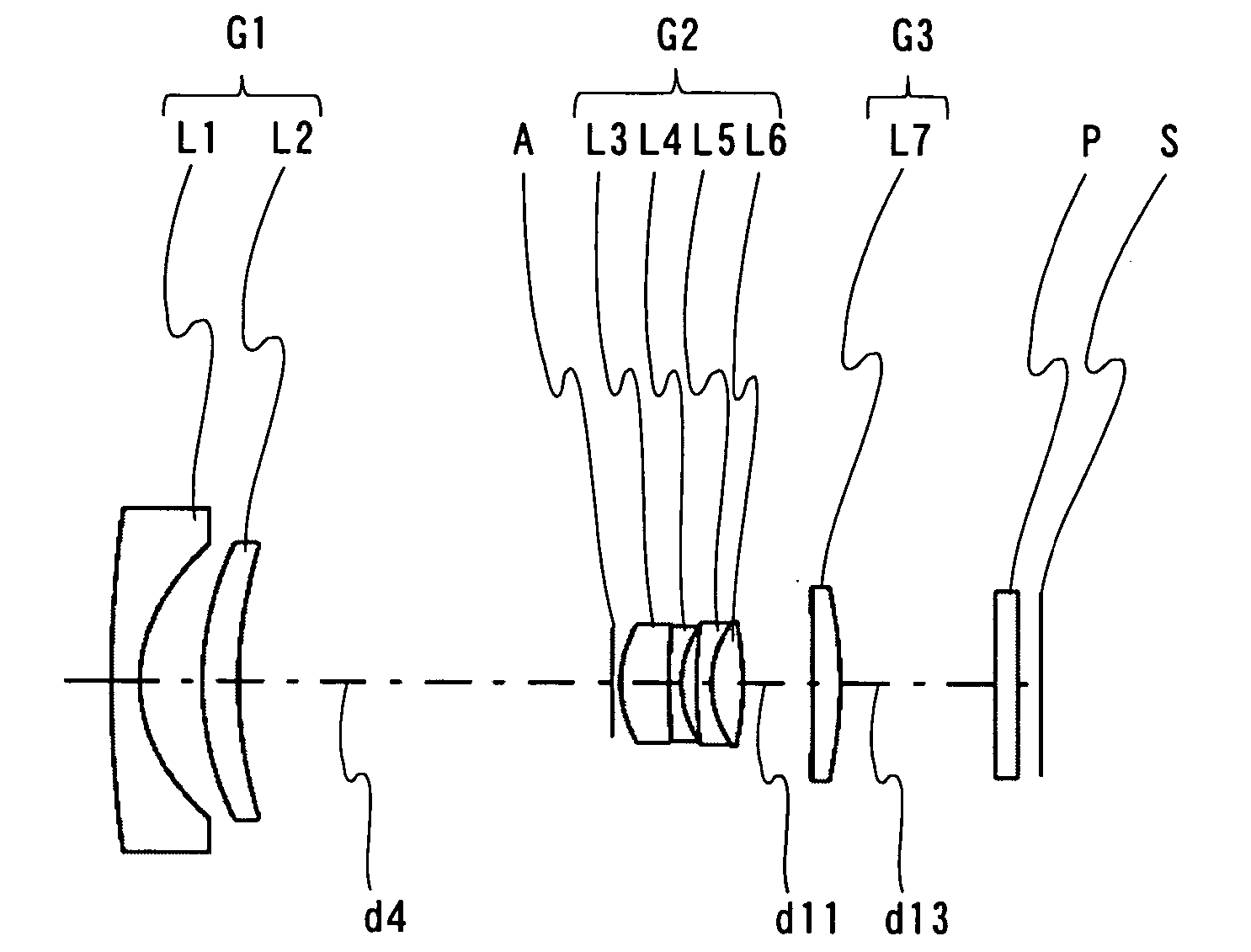
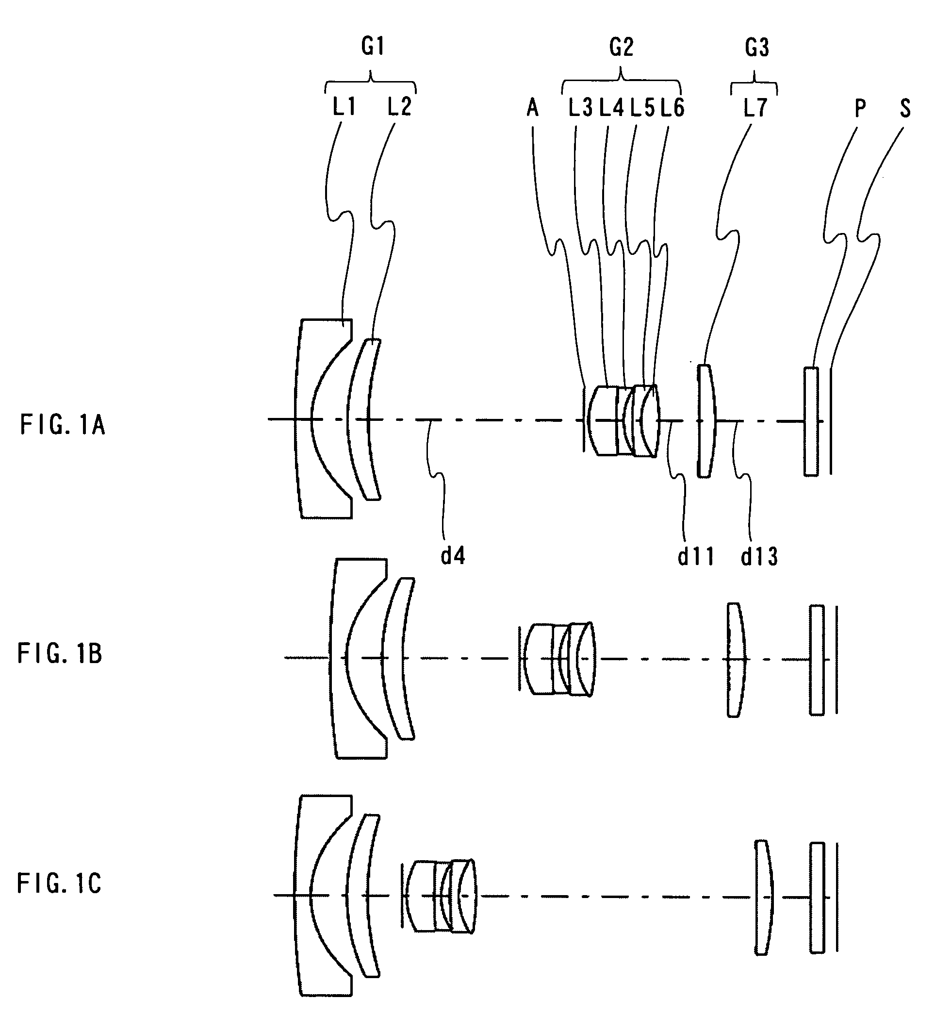
[0061]FIGS. 1A to 1C are configuration diagrams of a zoom lens system according to Embodiment 1. FIGS. 3A to 3C are configuration diagrams of a zoom lens system according to Embodiment 2. FIGS. 5A to 5C are configuration diagrams of a zoom lens system according to Embodiment 3. FIGS. 7A to 7C are configuration diagrams of a zoom lens system according to Embodiment 4. Each of FIGS. 1A to 1C, 3A to 3C, 5A to 5C, and 7A to 7C shows a zoom lens system in an infinity in-focus condition. FIGS. 1A, 3A, 5A and 7A show the lens construction at a wide-angle limit (the shortest focal length condition: focal length fW). FIGS. 1B, 3B, 5B and 7B show the lens construction at a middle position (the middle focal length condition: focal length fM=√{square root over ( )}(fW*fT)). FIG. 1C, 3C, SC and 7C show the lens construction at a telephoto limit (the longest focal length condition: focal length fT).
[0062] Each zoom lens system according to Embodiments 1 to 4, in order from the object side to the...
embodiment 5
[0116]FIG. 9 is a schematic construction diagram of a digital still camera according to Embodiment 5. In FIG. 9, the digital still camera comprises: an imaging device including a zoom lens system 1 and an image sensor 2 that is a CCD; a liquid crystal display monitor 3, and a body 4. The employed zoom lens system 1 is the zoom lens system according to Embodiment 1. In FIG. 9, the zoom lens system 1 comprises a first lens unit G1, a diaphragm A, a second lens unit G2, and a third lens unit G3. In the body 4, the zoom lens system 1 is arranged on the front side, while the image sensor 2 is arranged on the rear side of the zoom lens system 1. The liquid crystal display monitor 3 is arranged on the rear side of the body 4, while an optical image of a photographic object acquired through the zoom lens system 1 is formed on the image surface S.
[0117] The lens barrel comprises a main barrel 5, a moving barrel 6, and a cylindrical cam 7. When the cylindrical cam 7 is rotated, the first len...
example 1
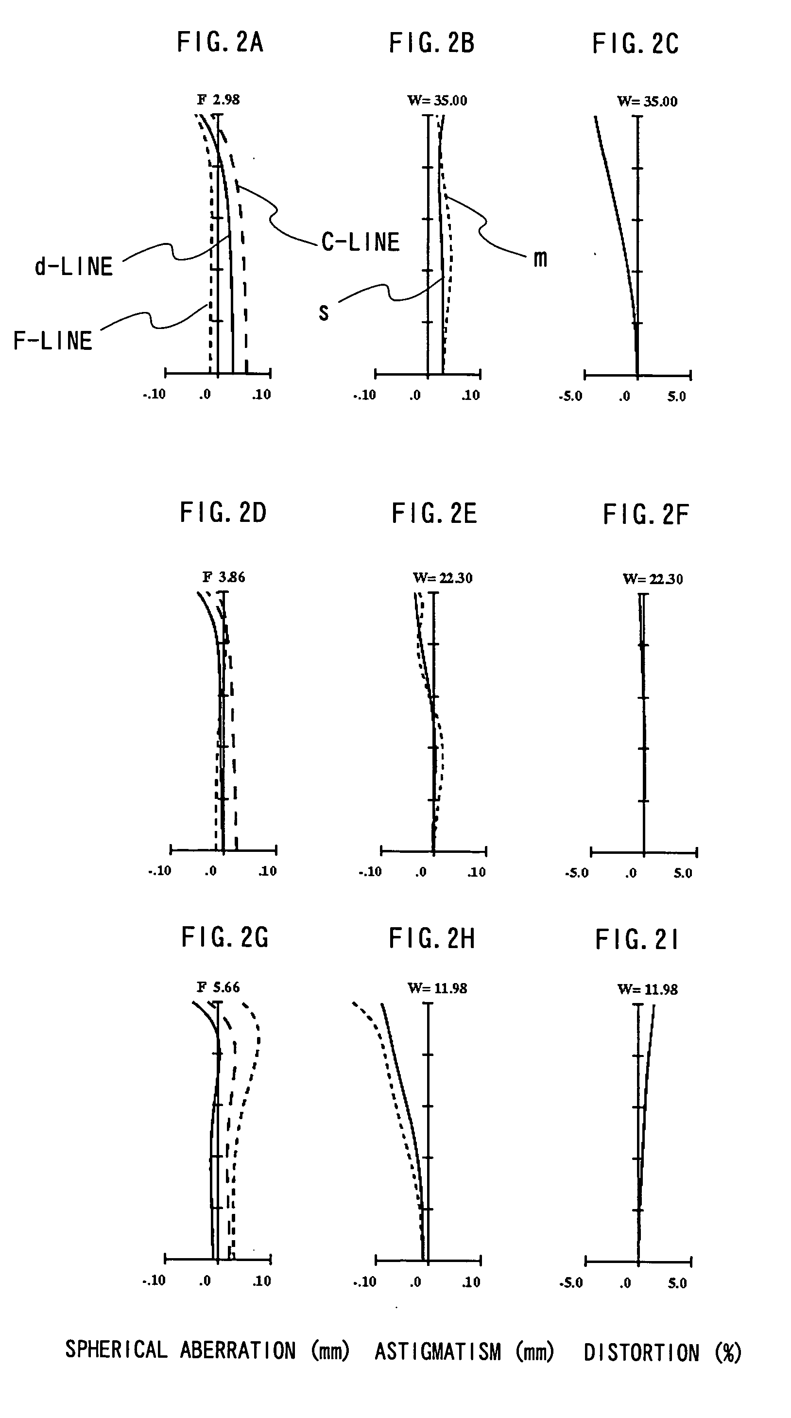
[0121] A zoom lens system of Example 1 corresponds to Embodiment 1 shown in FIGS. 1A to 1C. Table 1 shows the lens data of the zoom lens system of Example 1. Table 2 shows the aspherical data. Table 3 shows the focal length f, the F-number, the view angle 2ω, the overall optical length L, and the variable axial distance data d4, d11 and d13, when the shooting distance is infinity.
TABLE 1LensLens unitelementSurfacerdndν dG1L1 151.8241.1001.80541.0*26.2872.433L2 312.8871.4002.40017.0*417.651VariableDiaphragm 5∞0.300G2L3*64.6171.9001.80541.0L4 730.1910.5001.71729.5 84.0690.600L5 919.2890.6001.62036.3L6104.4131.2001.58961.311−12.764VariableG3L712−237.8731.1001.66555.2*13 −15.297VariableP14∞0.9001.51764.215∞0.870
[0122]
TABLE 2SurfacekABCDE2−3.612E−01 7.170E−06−3.185E−06−1.903E−09 −1.340E−090.000E+0040.000E+00−9.258E−05 1.154E−060.000E+00 0.000E+000.000E+0060.000E+00−5.397E−04−1.839E−051.169E−07−3.148E−080.000E+00130.000E+00 4.422E−04−5.274E−056.216E−06−3.426E−077.090E−09
[0123]
TABLE 3Ax...
PUM
 Abstract
Description
Claims
Application Information
 - R&D
- Intellectual Property
- Life Sciences
- Materials
- Tech Scout
- Unparalleled Data Quality
- Higher Quality Content
- 60% Fewer Hallucinations
Browse by: Latest US Patents, China's latest patents, Technical Efficacy Thesaurus, Application Domain, Technology Topic, Popular Technical Reports.
© 2025 PatSnap. All rights reserved.Legal|Privacy policy|Modern Slavery Act Transparency Statement|Sitemap|About US| Contact US: help@patsnap.com