Communication apparatus, integrated circuit, and communication method

a communication apparatus and integrated circuit technology, applied in power distribution line transmission, powerline communication applications, frequency-division multiplexes, etc., can solve problems such as inability to perform data transmission, communication errors, adverse effects of increasing workload, etc., to achieve the effect of easy detection of signals outpu

Active Publication Date: 2007-05-31
PANASONIC CORP
View PDF21 Cites 36 Cited by
  • Summary
  • Abstract
  • Description
  • Claims
  • Application Information

AI Technical Summary

Benefits of technology

[0011] An object of embodiments described in the following is to provide a communication apparatus, an integrated circuit and a communication method that are capable of easily detecting signals output from other communication apparatuses, even when a plurality of types of communication apparatuses using different communication methods are connected to a common transmission line, without performing relatively cumbersome modulation and other processes.

Problems solved by technology

This causes interference between signals transmitted from the plurality of types of communication apparatuses, thereby causing communication errors.
However, modulation processes performed to allow the plurality of types of communication apparatuses to coexist have an adverse effect of increasing the workload.
The second communication apparatus is incapable of performing the data transmission with said integrated circuit.

Method used


Image

  • Communication apparatus, integrated circuit, and communication method
  • Communication apparatus, integrated circuit, and communication method
  • Communication apparatus, integrated circuit, and communication method

Examples


first embodiment

[0042] The first embodiment is described in the following with reference to FIGS. 1 to 10.

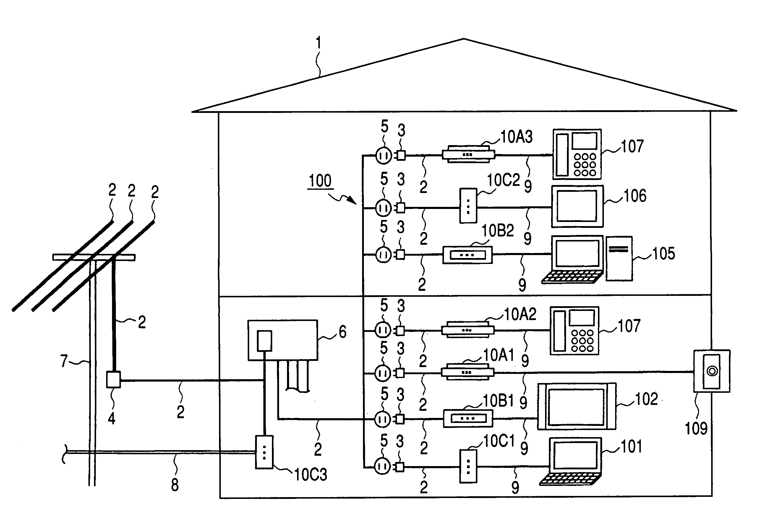
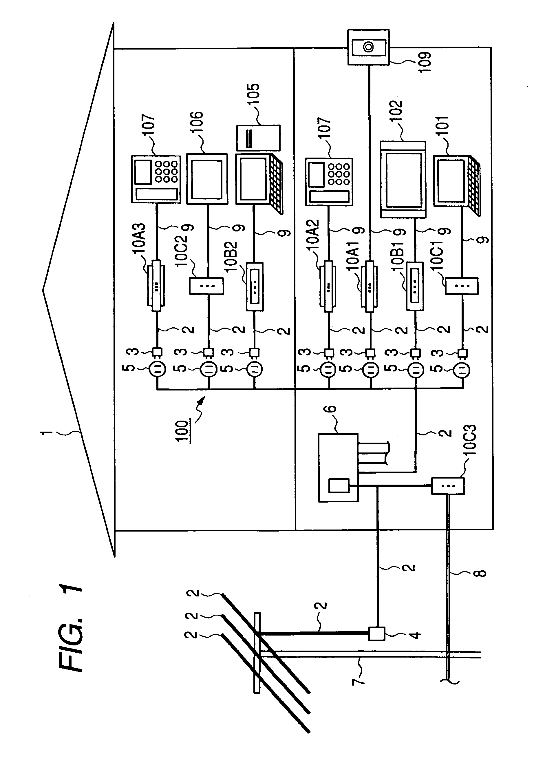
[0043]FIG. 1 is a schematic configuration view of communication system 100 according to the first embodiment. As shown in FIG. 1, communication system 100 includes a network using power lines 2 as transmission lines. Power lines 2 include: power transmission cables of power pole 7, which is provided outdoors; a pull-in cable connected to the power transmission cables via transformer 4; and an interior wiring within residence 1. Power lines 2, which include the power transmission cables, are connected to power distribution panel 6 via power lines 2, which include the pull-in cable. Fiber cable 8, which is connected to an ISP (Internet Service Provider / not shown), or the like, is connected to power distribution panel 6 via modem 10C3, which functions as a communication apparatus.

[0044] Power lines 2, which are connected to power distribution panel 6, are connected to a plurality of outlets 5 in...

second embodiment

[0097] The second embodiment is described in the following with reference to FIGS. 1, 2, and 11 through 14.

[0098] Communication system 100 according to the second embodiment is identical to that described in the first embodiment, and its descriptions are thus omitted. The communication apparatus according to the second embodiment is the same modem 10 described in the first embodiment, and its description are thus omitted.

[0099]FIG. 11 is a block diagram illustrating a hardware example that constitutes modem 10 according to the second embodiment. Modem 10, as shown in FIG. 11, lacks sub IC 42, which is described in FIG. 3. Modem 10, as shown in FIG. 11, further lacks AFE IC 43, band-pass filters 45 and 49, and driver IC 46 (hereinafter these are referred to as “AFE circuit” that have been described in FIG. 3). In other words, modem 10 has the same components as described in the first embodiment except for the deleted sub IC 42 and AFE circuit, and its descriptions are thus omitted....

third embodiment

[0118] The third embodiment is described in the following with reference to FIGS. 15 through 17.

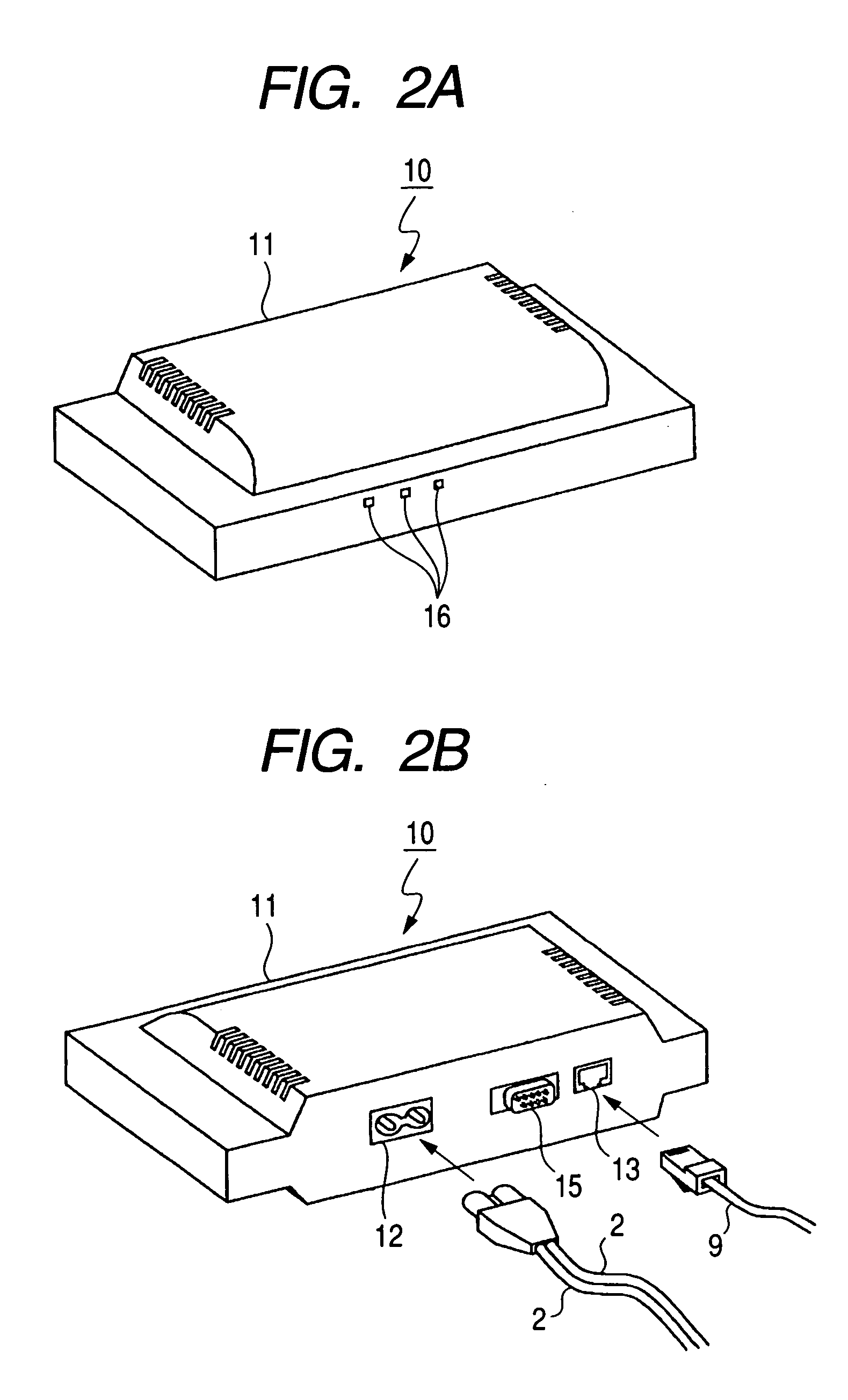
[0119] Communication system 100 according to the third embodiment is identical to that described in the first embodiment, and its descriptions are thus omitted. As shown in FIG. 2, the communication apparatus according to the third embodiment is identical to modem 10 according to the first embodiment, and its descriptions are thus omitted.

[0120]FIG. 15 is a block diagram illustrating a hardware example that constitutes modem 10 according to the third embodiment. In the circuit configuration shown in FIG. 15, zero cross circuit 63 is provided in modem 10 described in FIG. 3. The circuit configuration shown in FIG. 15 is identical to that described in FIG. 3 except for zero cross circuit 63, and PLC PHY block 42D (described later) of sub IC 42. Therefore, the same components are assigned the same numbers, and their descriptions are thus omitted.

[0121] Zero cross circuit 63 includes bridg...


PUM


Abstract

A communication apparatus repeatedly outputs a first multi-carrier signal SS during predetermined periods T1, T2, T3, . . . , and outputs a second multi-carrier signal RS whose phase vector is different from that of the first multi-carrier signal SS, at a predetermined timing based on the first multi-carrier signal SS. The communication apparatus further detects the second multi-carrier signal RS output from another communication apparatus, which uses a different communication method from the communication apparatus. Accordingly, both communication apparatuses can differentiate the first multi-carrier signal SS from the second multi-carrier signal RS without performing relatively cumbersome modulation and other processes.

Description

INCORPORATION BY REFERENCE [0001] This application is related to the following patent which is hereby incorporated by reference in its entirely: U.S. Pat. No. 6,944,232, RECEIVING APPARATUS AND METHOD FOR DIGITAL MULTI-CARRIER TRANSMISSION, Inventors: Hisao Koga et al., filed on Feb. 19, 2004.BACKGROUND [0002] 1. Field of the Invention [0003] The present invention relates to a communication apparatus, an integrated circuit and a communication method that are capable of easily detecting signals output from other communication apparatuses, which use different communication methods and are connected to a common transmission line, while avoiding interference between signals without performing relatively cumbersome modulation and other processes. [0004] 2. Description of Related Art [0005] With the recent development of communication technology, PLC (Power Line Communication) has been gaining attention. PLC is a technology that performs multi-carrier communications among a plurality of t...

Claims


Application Information

Patent Timeline
Patent Type & Authority Applications(United States)
IPC IPC(8): H04J1/00
CPCH04B3/54H04B2203/5408H04B2203/5445H04B2203/5454H04L5/0007H04B2203/542H04L5/0094H04L5/1438H04L27/0006H04B3/542H04L5/0032H04J1/00
Inventor KOGA, HISAOKODAMA, NOBUTAKA
Owner PANASONIC CORP
Why Eureka
Try Eureka