Virtual visual point image generating method and 3-d image display method and device

a virtual visual and point image technology, applied in static indicating devices, instruments, optical elements, etc., can solve the problems of large amount of data required for representing the three-dimensional object, inability to represent the detailed shape of the object, and not immediately obtain the geometric model of the object using the stereo method. , to achieve the effect of small partial low reliability of object shape estimation, and remarkable deterioration of image quality

Active Publication Date: 2007-05-31
NIPPON TELEGRAPH & TELEPHONE CORP
View PDF4 Cites 103 Cited by
  • Summary
  • Abstract
  • Description
  • Claims
  • Application Information

AI Technical Summary

Benefits of technology

[0099] According to the present invention, when generating the image of the object by obtaining the three-dimensional shape of the object from plural images, it becomes possible to reduce remarkable deterioration of image quality that occurs in a part where the reliability of estimation of the shape of the object is low. In addition, it b...

Problems solved by technology

But, the geometrical model of the object is not immediately obtained using the stereo method.
However, when the geometrical model of the object is represented by the voxels, large amount of data are required for representing the three-dimensional shape of the o...

Method used


Image

  • Virtual visual point image generating method and 3-d image display method and device
  • Virtual visual point image generating method and 3-d image display method and device
  • Virtual visual point image generating method and 3-d image display method and device

Examples


first embodiment

[0210] First, the first embodiment of the present invention is described. The first embodiment mainly corresponds to claims 1-11. In this embodiment, although three primary colors of red (R), green (G) and blue (B) are used for representing color information as an example, other representation such as brightness (Y) or color difference (U, V) can be used. In addition, for black-and-white images, only brightness information can be used as the color information. In figures for explaining the first embodiment, the same reference signs are assigned for the same functions.

[0211] Before explaining each embodiment of the first embodiment, principle of a virtual viewpoint image generation method of the first embodiment is described.

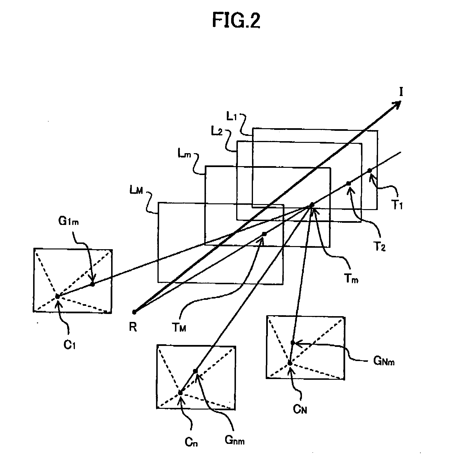
[0212]FIGS. 2-5 are schematic diagrams for explaining the principle of the virtual viewpoint image generation method of the present invention. FIG. 2 shows examples of projection plane group, camera, reference viewpoint, projection point and corresponding point...

embodiment 1-1

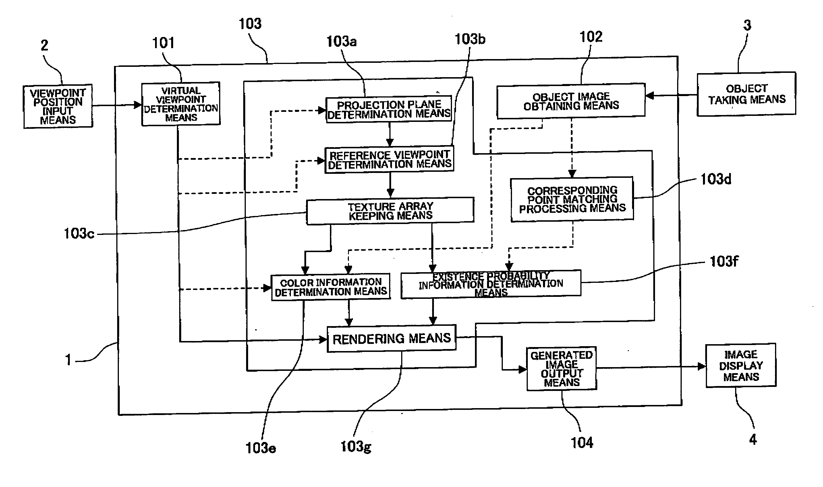
[0241]FIGS. 6 and 7 are a schematic diagram showing an outline configuration of a virtual viewpoint image generation apparatus of the embodiment 1-1 of the present invention. FIG. 6 is a block diagram showing a configuration of the inside of an image generation apparatus, and FIG. 7 is a configuration example of a system using the image generation apparatus.

[0242] In FIG. 6, 1 indicates a virtual viewpoint image generation apparatus, 101 indicates a virtual viewpoint determination means, 102 indicates an object image obtaining means, 103 indicates an image generation means, 103a indicates a projection plane determination means, 103b indicates a reference viewpoint determination means, 103c indicates a texture array keeping means, 103d indicates a corresponding point matching processing means, 103e indicates a color information determination means, 103f indicates an existence probability information determination means, 103g indicates a rendering means, 104 indicates a generated ima...

embodiment 1-2

[0303]FIGS. 19A and 19B are schematic diagrams for explaining a virtual viewpoint image generation method of the embodiment 1-2. FIG. 19A is a flow diagram indicating processing that is a feature of this embodiment 1-2. FIG. 19B is a flow diagram showing an example of concrete processing procedure of steps for determining transparency information.

[0304] In the embodiment 1-2, an example is described in which image generation is performed by converting the existence probability information into transparency information instead of using the existence probability information of the projection point calculated in the step 503l in generation processing for virtual viewpoint image described in the embodiment 1-1.

[0305] In this example, as to the configuration of the virtual viewpoint image generation apparatus 1 and the general processing procedure, forms similar to examples described in the embodiment 1-1 can be adopted. Thus, only parts having differences with respect to the embodimen...


PUM


Abstract

A virtual viewpoint image generation method for generating a virtual viewpoint image that is an image of an object viewed from a virtual viewpoint based on plural images of the object taken by plural cameras is provided. In the virtual viewpoint image generation method, projection planes having a multi-layered structure are set, each corresponding point, on the images of the object, corresponding to a projection point of a projection plane is obtained, color information of each projection point is determined based on color information of corresponding points, for each of the projection points overlapping when viewed from a reference viewpoint in a space, a degree of probability that the object exists at a distance corresponding to a position of the projection point is determined based on a degree of correlation of the corresponding points, mixing processing is performed on color information of reference points overlapping when viewed from the virtual viewpoint according to the degree of probability of existence of the object so as to determine color information of each pixel of the virtual viewpoint image.

Description

TECHNICAL FIELD [0001] The present invention relates to a technology for estimating information on a three-dimensional shape of an object from plural images to generate an image using the information. The technology of the present invention can be applied to a system that supports visual communications such as a TV phone and the like. BACKGROUND ART [0002] From the past, in the fields of the computer graphics (CG) and the virtual reality (VR), technologies have been activity studied for generating an image of an object, by a computer, viewed not only from a viewpoint position at which a camera is placed but also from a viewpoint position desired by a user. [0003] For example, there are methods for displaying a three-dimensional image of an object or generating an image (to be referred to as a virtual viewpoint image hereinafter) of an object viewed from a virtual viewpoint using plural images of the object taken under different conditions. [0004] As a method for displaying a three-d...

Claims


Application Information

Patent Timeline
IPC IPC(8): G06K9/00G02B27/22G06T7/00H04N13/00
CPCG02B27/2271G06T7/0075G06T15/205H04N13/0242G06T7/593G02B30/50H04N13/243G06T17/00H04N13/00
Inventor KUNITA, YUTAKAHASHIMOTO, AKIHIKOSUYAMA, SHIRO
Owner NIPPON TELEGRAPH & TELEPHONE CORP
Why Eureka
Try Eureka