Device for the absolute measurement of the linear or rotational position of an object

Inactive Publication Date: 2007-05-31
SICK STEGMANN
View PDF7 Cites 0 Cited by
  • Summary
  • Abstract
  • Description
  • Claims
  • Application Information

AI Technical Summary

Benefits of technology

[0004] The invention is based on the problem of creating a device which records the object's position in coded fashion ov

Problems solved by technology

In these known devices a problem is posed by the abrasion or wear that is experienced by the effective mechanical link, particularly by the gearings that engage with

Method used


Image

  • Device for the absolute measurement of the linear or rotational position of an object
  • Device for the absolute measurement of the linear or rotational position of an object

Examples


Embodiment Construction

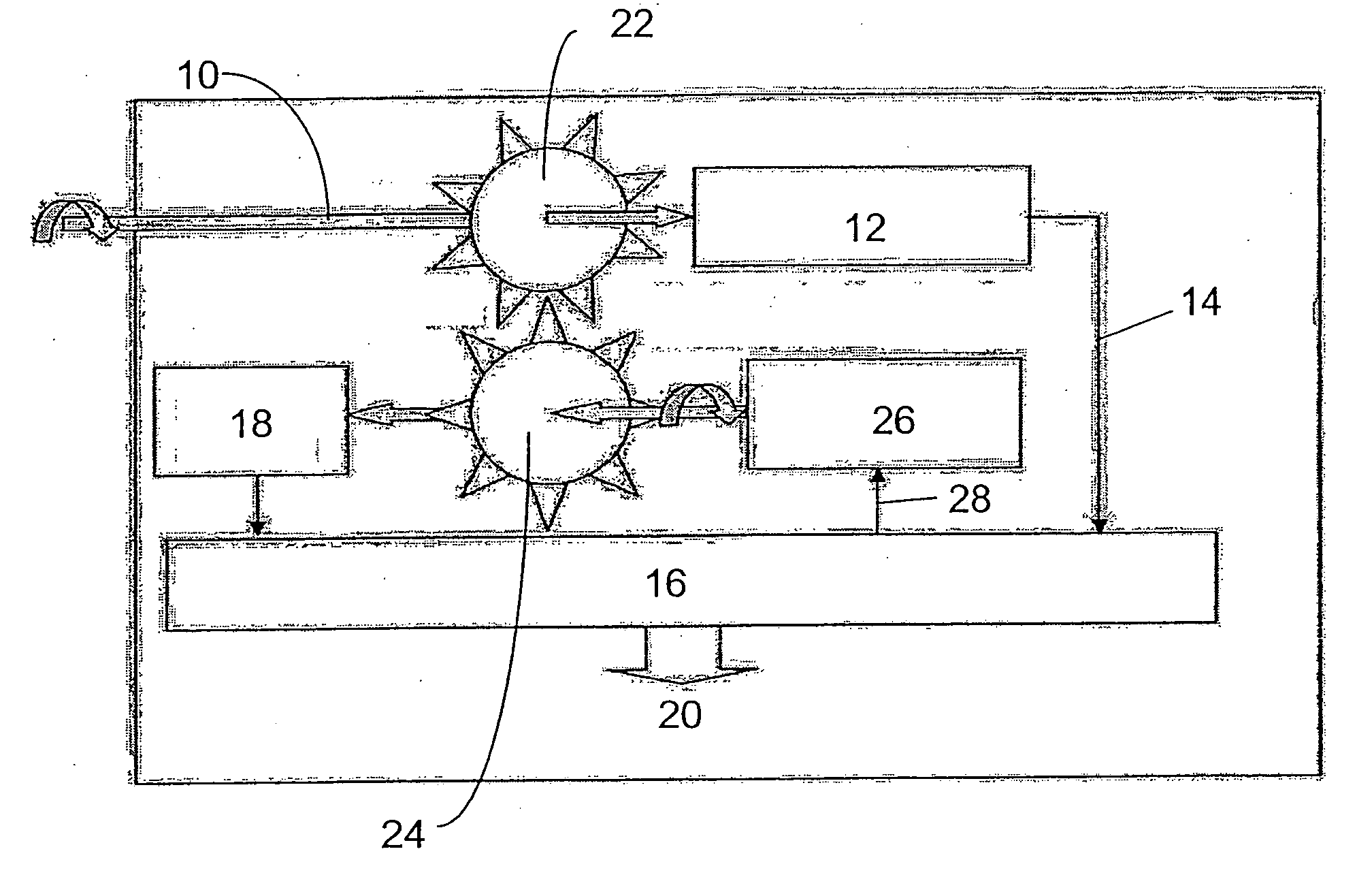
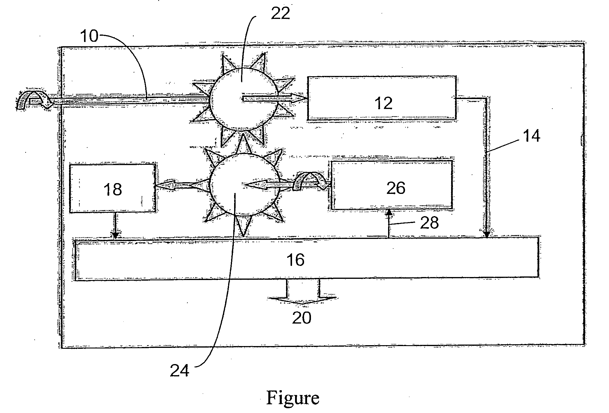
[0009] Next the invention will be described in greater detail on the basis of an exemplary embodiment, which is depicted schematically in the single FIGURE of the attached drawing.

[0010] In the schematic depiction the absolute angular position of a measured object 10 is be measured over a number of rotations. The measured object 10 can be, e.g., the shaft of a servomotor or a rotating object that requires positioning. The measured object 10 can also be the input shaft of a positional indicator, which is coupled to such a servomotor shaft or such an object being positioned.

[0011] Coupled to the measured object 10 in angularly secure fashion is a material measure, which the figure does not depict. The material measure can be, e.g., a coding disk, which is connected to the measured object 10 in torque-proof fashion and is scanned either optically, magnetically, or in some other fashion. The scanner 12 detects in absolute fashion the angular position of the material measure, and thus ...


PUM


Abstract

In the absolute measurement of the position of an object (10) over a plurality of cyclical scannings performed on a material measure, a coding unit (18) is employed to record the cycles. The coding unit (18) is coupled to the measured object (10) by an effective mechanical link (22, 24). The effective link consists of a driving gearwheel (22) and a driven input wheel (24), which belongs to the coding unit (18). To minimize wear on the toothed connection, the connection is allowed a large degree of play and the driven input wheel (24) is run by a motor (26) synchronously with the drive gearwheel (22), as controlled by the scanner (12). The result is that the effective connection occurs within the area of play, without mechanical engagement of the toothings.

Description

FIELD OF THE INVENTION [0001] The invention relates to a device for the absolute measurement of the linear or rotational position of an object, in accordance with the preamble of patent claim 1. BACKGROUND OF THE INVENTION [0002] To measure the linear or rotational position of an object it is known to couple the measured object with a material measure, which is scanned cyclically by a scanner. When the measured object is a rotating one it is thereby possible to determine the absolute position over several revolutions of the object. When the measured object moves in linear fashion a periodically returning material measure can be scanned over several periods. Here a device is used which records the object's position in coded fashion over a plurality of scanned cycles. To this end, the coding unit exhibits an input wheel, which is coupled to the measured object by an effective mechanical link. The effective mechanical link is generally realized by a toothed gearing. When the object bei...

Claims


Application Information

Patent Timeline
IPC IPC(8): G01C21/00
CPCG01D5/04G01D5/08G01D5/24433
Inventor SIRAKY, JOSEF
Owner SICK STEGMANN
Why Eureka
Try Eureka