Device for aligning two shell molds

a technology for aligning devices and shell molds, applied in the direction of dough shaping, manufacturing tools, instruments, etc., can solve the problem of over-determined centering devices

Inactive Publication Date: 2007-06-07
INTERGLASS TECHNOLOLGY AG
View PDF11 Cites 26 Cited by
  • Summary
  • Abstract
  • Description
  • Claims
  • Application Information

AI Technical Summary

Benefits of technology

[0004] An object of the invention is to develop a device for the mutual alignment and positioning of two shell molds that enables high centering accuracy.
[0005] The device in accordance with the invention comprises a first gripper for holding the first shell mold and a second gripper for holding the second shell mold and a centering station. The two grippers can be moved relative to each other and relative to the centering station along a predetermined axis and can be rotated individually as well as synchronously on the axis. The centering station consists of a supporting body that supports at least one spring element arranged along a circle whereby the axis runs through the center of the circle. For centering, the shell mold is moved into the centering station by the gripper whereby the spring element or spring elements are deflected or deformed depending on their actual structure and then released from the gripper so that the shell mold is only held by the spring element or spring elements. The radial forces from the spring element or spring elements acting uniformly on the shell mold from all sides have the effect that the shell mold is moved into the force center of gravity so that it is centered in relation to the axis. The shell mold is then grasped again by the gripper and moved out of the centering station. The device in accordance with the invention has the advantage that the two grippers have the centering axis of the centering station as common axis.
[0006] In accordance with a first embodiment, the supporting body is a body with a wall that forms a circular opening through the center of which the axis runs. The wall has a groove. An O-ring, a cord, a tube or a thing like that made of elastically deformable material is inserted into the groove. With this example, the groove is circular and supports the O-ring, cord or tube uniformly along the circle. With O-ring, is meant a conventional, closed O-ring as well as a cut O-ring that one could refer to as round cord. One can consider the O-ring, the cord or the tube as one single spring element or also as a number of spring elements that continuously merge. The O-ring or the round cord touches the shell mold along its perimeter and the radial forces acting uniformly on the shell mold from all sides have the effect that the center of the shell mold moves into the force center of gravity.
[0014] Preferably, an adhesive tape known in the art as a tape serves as the sealing element. The tape is an element joining the two shell molds that on the one hand has a low rigidity so that it can easily be stuck to the two shell molds and on the other hand is sufficiently rigid so that the composite formed is adequately stable. The tape ensures that the alignment of the shell molds relative to each other does not change or only changes negligibly when the composite is transported to the filling station where the lens is produced by casting a monomer.

Problems solved by technology

The disadvantage with this device is that the centering device is overdetermined because the position of a shell mold is determined by means of four contact points although three contact points would be sufficient.
A further disadvantage is that, after centering, the shell molds have to be transported and aligned on a common axis before they can be joined together with the tape.

Method used


Image

  • Device for aligning two shell molds
  • Device for aligning two shell molds
  • Device for aligning two shell molds

Examples


Embodiment Construction

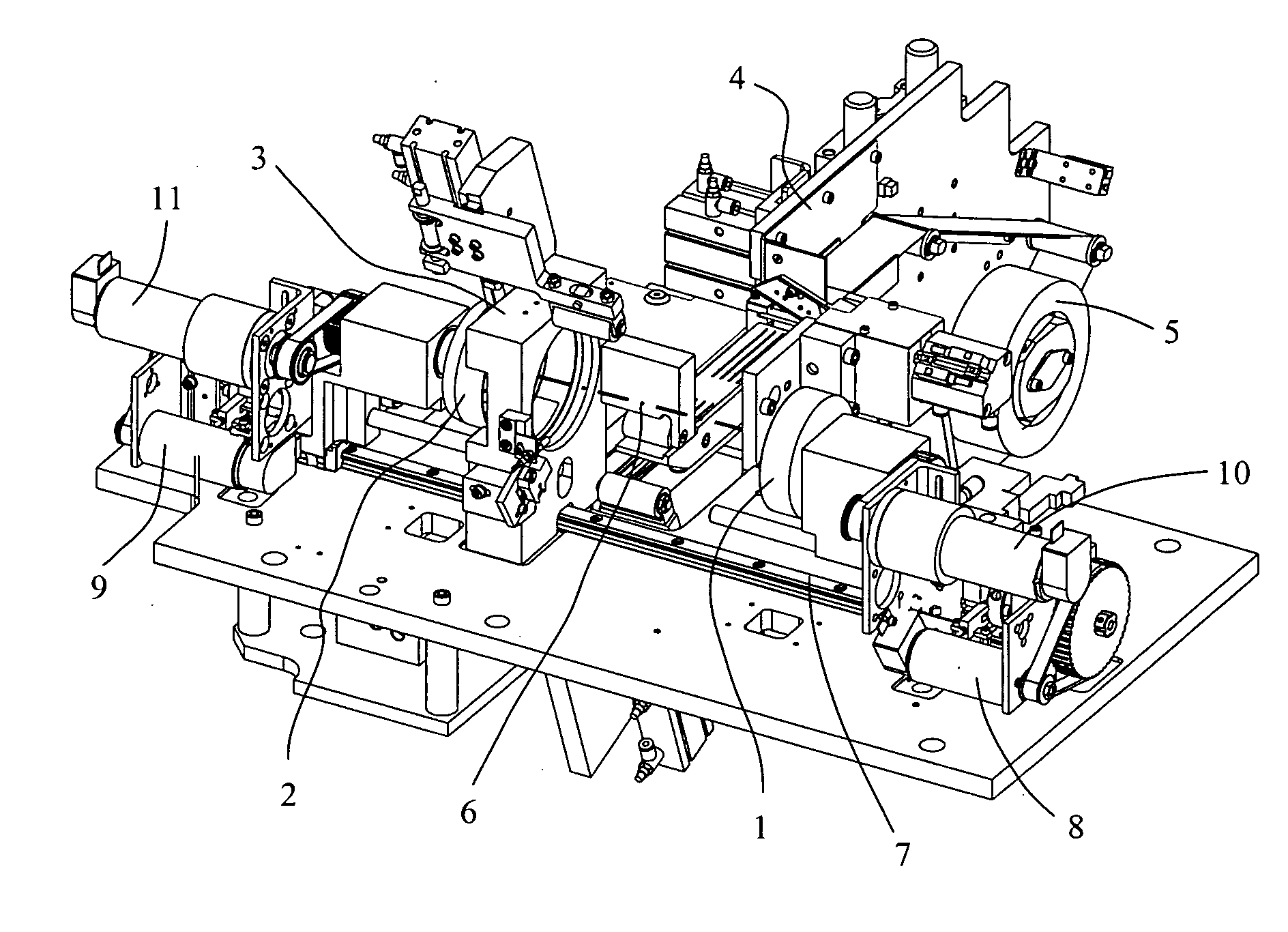
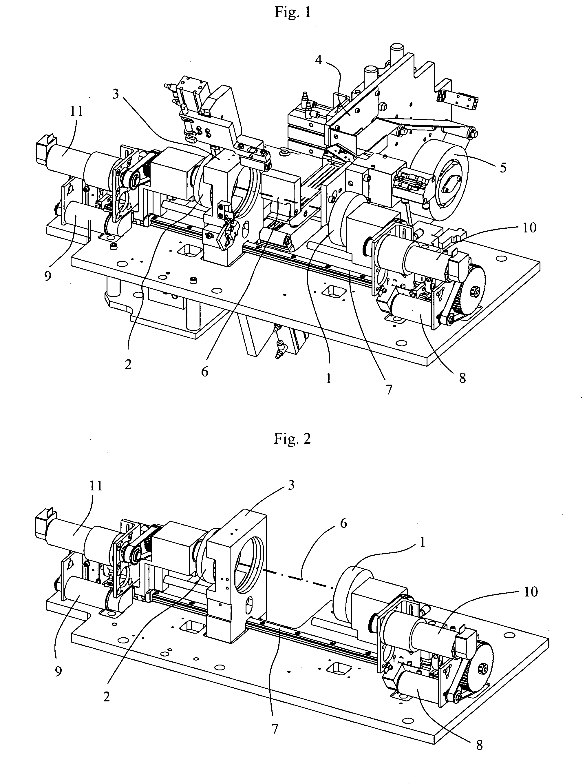
[0026]FIGS. 1 and 2 show a perspective view of a device that serves to align the optical axes of a first shell mold and a second shell mold relative to each other and to position them at a predetermined distance and then to join them together into a composite by means of sticking a tape along the edge of the two shell molds. FIG. 1 shows the entire device with the device for applying the tape. FIG. 2 shows the same device for reasons of illustrative clarity without the device for applying the tape. The device comprises a gripper 1 for holding the first shell mold, a gripper 2 for holding the second shell mold, a centering station 3 and a device 4 for feeding and applying the tape 5. The two grippers 1 and 2 can be moved along a predetermined axis 6 and can be rotated on the axis 6 individually as well as together. The two grippers 1 and 2 preferably bear on a common guide rail 7. The axis 6 runs parallel to the guide rail 7. A first motor 8 serves to move the first gripper 1 along t...


PUM

PropertyMeasurementUnit
distanceaaaaaaaaaa
opticalaaaaaaaaaa
gravityaaaaaaaaaa

Abstract

A device for aligning a first and a second shell mold comprises a first gripper for holding the first shell mold, a second gripper for holding the second shell mold, and a centering station. Both grippers can be displaced relative to one another and relative to the centering station along a predetermined axis and can rotate individually as well as synchronously about the axis. The centering station comprises a supporting body, which supports spring elements arranged along a circle, said axis running through the center of the circle. For centering, the shell mold is moved into the centering station by the gripper and then removed from the gripper so that the shell mold is held solely by the spring elements. The radial forces of the spring elements uniformly acting upon the shell mold from all sides cause the shell mold to be displaced into the center of gravity of the forces. Afterwards, the shell mold is gripped once again by the gripper and moved out from the centering station.

Description

CROSS REFERENCE TO RELATED APPLICATIONS [0001] The present application is related to and claims priority of the PCT application number PCT / EP2005 / 052897 entitled Device for aligning two shell molds, filed Jun. 21, 2005, the disclosure of which is herein incorporated by reference, which in turn claims priority of the European patent application No. 04103123.8 filed Jul. 2, 2004. TECHNICAL FIELD [0002] The invention concerns a device for aligning two shell molds. TECHNICAL BACKGROUND [0003] Such shell molds are used for the manufacture of optical lenses. In doing so, a monomer is cast in a cavity bordered by two shell molds and a seal and then polymerised, whereby the lens is produced. From U.S. Pat. No. 5,178,801 it is known to center a front shell mold and a rear shell mold in one centering device each, then to arrange them at a predefined distance on a common axis and to join them together into a composite by means of a tape. In the centering devices, the optical axes of the shell ...

Claims


Application Information

Patent Timeline
Patent Type & Authority Applications(United States)
IPC IPC(8): B23P19/00B29C33/30B29D11/00
CPCB29D11/00413Y10S425/808Y10T29/53B29D11/00528
Inventor PROBST, URS
Owner INTERGLASS TECHNOLOLGY AG
Why Eureka
Try Eureka