Hydraulic tensioning clamping mandrel for thin-wall shaft sleeve

A clamping and hydraulic technology, which is applied in the direction of expanding the mandrel, etc., can solve the problems of complex structure and difficult manufacturing of the spring sleeve mandrel and liquid plastic mandrel, and achieve accurate operation accuracy, stability and reliability, low cost, The effect of simple structure

Inactive Publication Date: 2016-04-06
SICHUAN LINGFENG AVIATION HYDRAULIC MACHINERY
View PDF8 Cites 9 Cited by
  • Summary
  • Abstract
  • Description
  • Claims
  • Application Information

AI Technical Summary

Problems solved by technology

The third is that the spring sleeve mandrel and the liquid plastic mandrel have complex structures and are difficult to manufacture

Method used


Image

  • Hydraulic tensioning clamping mandrel for thin-wall shaft sleeve
  • Hydraulic tensioning clamping mandrel for thin-wall shaft sleeve
  • Hydraulic tensioning clamping mandrel for thin-wall shaft sleeve

Examples


Embodiment Construction

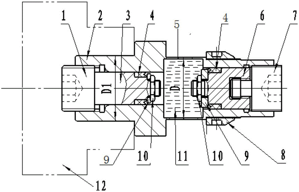
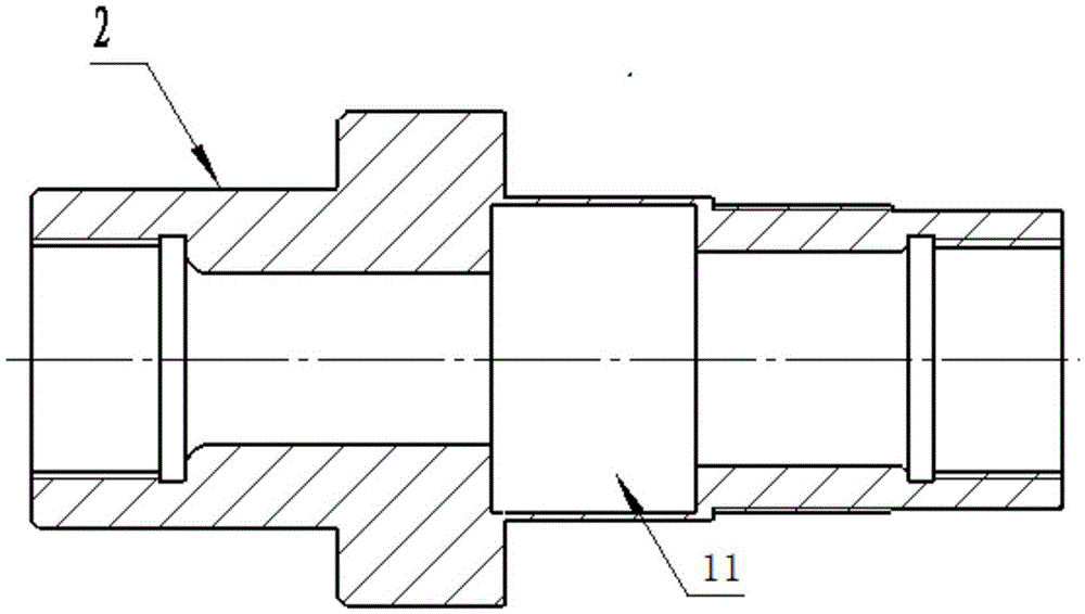
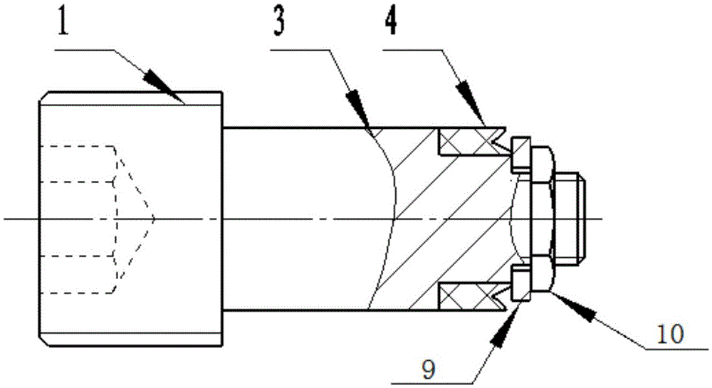
[0014] exist figure 1 , figure 2 Among them, the thin-walled shaft sleeve hydraulic tensioning clamping mandrel has a mandrel 2 positioned on the end face of the machine tool chuck or spring sleeve 14, the mandrel 2 is made with a stepped shaft platform for positioning the end face of the part to be processed, and the two ends are made of There is a stepped hole for assembling the plunger and a hydraulic oil chamber connected to the stepped hole, wherein the left pressure regulating plunger 3 is sealed to the left end of the hydraulic oil chamber from the left side of the mandrel to the stepped hole, and the right pressure regulating plunger 6 is sealed from the core to the left end of the hydraulic oil chamber. The right step hole of the shaft is sealed at the right end of the hydraulic oil chamber, and the parts to be processed assembled on the right side of the mandrel are clamped between the end surface of the mandrel step shaft platform and the compression nut 10 through...


PUM


Abstract

The invention discloses a hydraulic tensioning clamping mandrel for a thin-wall shaft sleeve. The hydraulic tensioning clamping mandrel is provided with a mandrel body located to the end face of a machine tool chuck or a spring sleeve. A step shaft table for locating the end face of a part to be machined is manufactured on the mandrel body, and step holes for assembling of plungers and a hydraulic oil cavity communicated with the step holes are formed in the two ends. The left pressure adjusting plunger (3) is sealed at the left end of the hydraulic oil cavity from the leftward step hole of the mandrel body (2), the right pressure adjusting plunger (6) is sealed at the right end of the hydraulic oil cavity from the rightward step hole of the mandrel body, and a closed container is formed. The to-be-machined part assembled on a rightward barrel of the mandrel body is clamped between the end face of the step shaft table of the mandrel body and a compressing nut (10) through the compressing nut (10). Sealing screws (7) are screwed down to drive the plungers to move and compress hydraulic oil in the hydraulic oil cavity, and the to-be-machined part clamped on the external circle tensioning mandrel body on the thin wall of the hydraulic oil cavity is expanded through pressure generated by the hydraulic oil cavity under the action of oil pressure. The hydraulic tensioning clamping mandrel is easy to manufacture and high in clamping precision, and a clamping area is stable and reliable in clamping.

Description

technical field [0001] The invention relates to a lathe clamping tool which uses the size of the inner hole of a part as a positioning reference to process the end to the two sides of a large outer ring. Background technique [0002] In the process of mechanical manufacturing, we often encounter some thin-walled shaft sleeve parts that require high precision. The commonly used mechanical expansion mandrel can not meet such processing requirements, and the rigid mandrel with taper is easy to deform the workpiece. In daily production we come across such a part: in some cases, there are concentric but different diameter holes on the workpiece. For example, the material is 7050 duralumin, and the two sides of the large outer ring are processed based on the size of the inner hole of the part. The runout of both sides facing the positioning hole must be ≤0.02; and the coaxiality of the outer circle and the groove to the positioning hole must be ≤φ0.015. Similarly, the circular ...

Claims


Application Information

Patent Timeline
Patent Type & Authority Applications(China)
IPC IPC(8): B23B31/40
CPCB23B31/40
Inventor 韩俊峰王连杰杨涌曾德刚
Owner SICHUAN LINGFENG AVIATION HYDRAULIC MACHINERY
Why Eureka
Try Eureka