Tool holder for grooving cutting blade

A cutting insert and groove machining technology, applied in the direction of tools, tool holders, tool holder accessories for lathes, etc., can solve the problems of reducing tool service life, rapid wear of the tool body, fatigue damage, etc. and the ability to resist plastic deformation, prevent the reduction of positioning contact area, and increase the effect of positioning stability

Active Publication Date: 2012-07-25
ZHUZHOU CEMENTED CARBIDE CUTTING TOOLS CO LTD
View PDF10 Cites 5 Cited by
  • Summary
  • Abstract
  • Description
  • Claims
  • Application Information

AI Technical Summary

Problems solved by technology

The line contact position between the cutter body and the blade is at the middle position and the edge position of the upper and lower concave surfaces. When the line contact is at the middle side of the cutter body, the cutter body will lose the positioning effect of the side direction. When the cutting tool is cutting sideways, the cutter body Unstable clamping will cause rapid wear or fatigue damage of the cutter body; when the line contact is at the edge of the side plane of the cutter body, the edge load on the upper and lower concave surfaces of the cutter body is too large, because the wall thickness between the upper and lower concave surfaces of the cutter body and the side is too small, The shear stress on the upper and lower concave surfaces of the cutter body is too large, which can easily cause plastic deformation of the upper and lower concave surfaces of the blade
When the upper and lower concave surfaces of the cutter body and the protruding parts of the blade play a positioning role, the clamping of the cutter body is unstable, the blade is separated from the cutter body during cutting, and the cutter body replaces the blade to participate in cutting, causing damage to the cutter body and reducing the service life of the tool

Method used


Image

  • Tool holder for grooving cutting blade
  • Tool holder for grooving cutting blade
  • Tool holder for grooving cutting blade

Examples


Embodiment Construction

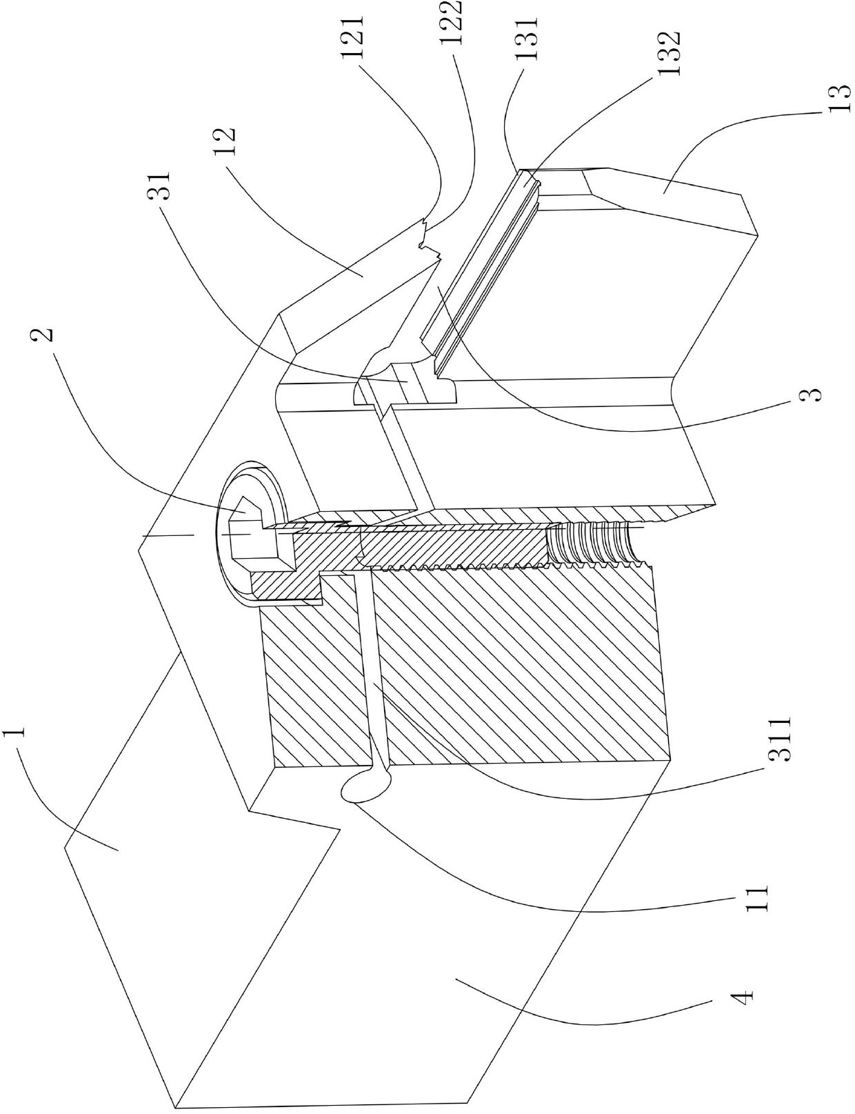
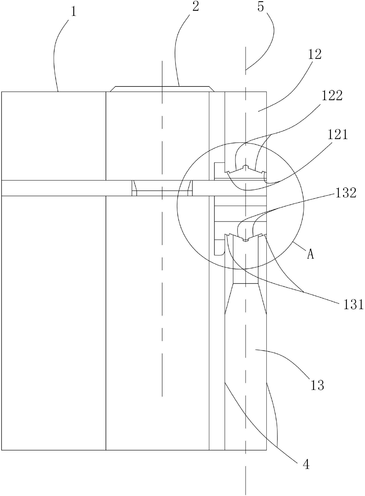
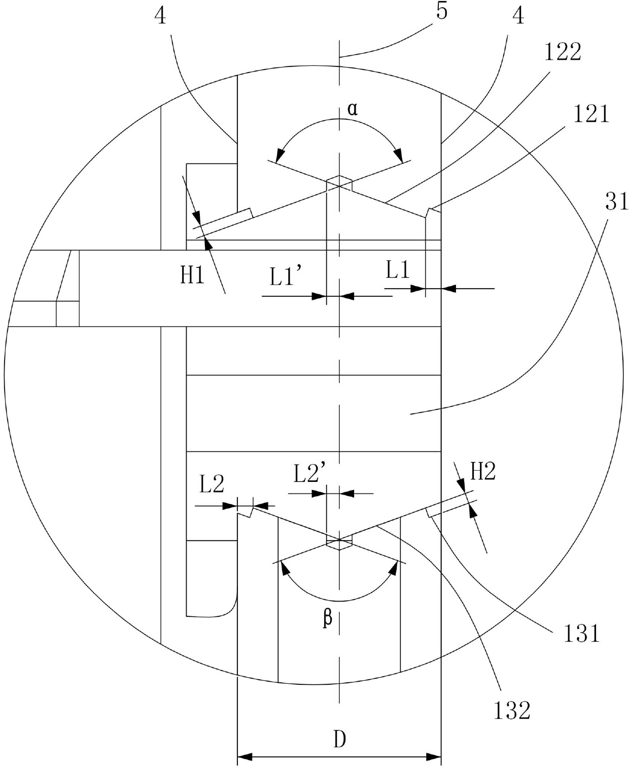
[0027] Figure 1 to Figure 3 It shows the first embodiment of the tool holder for grooving cutting inserts of the present invention, which includes a tool holder body 1 and a fastener 2, and the clamping part of the tool holder body 1 is composed of an upper clamping part 12 and a lower clamping part 12. The supporting part 13 is formed, and the upper positioning surface 121 of the upper clamping part 12 and the lower positioning surface 131 of the lower supporting part 13 encircle a blade clamping groove 3, and the rear end of the blade clamping groove 3 is provided with a rear supporting surface 31 and elastic The extension section 311, the elastic extension section 311 extends backward to the neck 11 of the tool holder body 1, the fastener 2 passes through the elastic extension section 311 to connect the upper and lower parts, the upper positioning surface 121 and the lower positioning surface 131 are installed The direction of the blade 6 is recessed inwardly, the upper po...


PUM


Abstract

The invention discloses a tool holder for grooving a cutting blade. The tool holder comprises a tool holder body and a fastener, a clamping portion of the tool holder body consists of an upper clamping portion and a lower supporting portion, an upper positioning surface of the upper clamping portion and a lower positioning surface of the lower supporting portion enclose a blade clamping groove, a rear supporting surface and an elastic extending section are arranged at the rear end of the blade clamping groove, the elastic extending section extends backwards to the neck of the tool holder body, the fastener penetrates through the upper portion and the lower portion of the elastic extending section, M discontinuous upper positioning tables are arranged on the upper positioning surface, and N discontinuous lower positioning tables are arranged on the lower positioning surface, wherein 2<=M<=6, and 2<=N<=6. The tool holder for grooving the cutting blade has the advantages that positioning positions and angles can be automatically adjusted, plastic deformation of the tool body can be effectively suppressed, and the tool holder is stable in structure and long in service life.

Description

technical field [0001] The invention relates to the field of metal cutting, in particular to a tool holder for cutting inserts for groove processing. Background technique [0002] The positioning of the tool holder for cutting inserts for grooving in the up and down direction of the cutter body is realized through the upper and lower positioning surfaces of the cutter body. According to the shape of the positioning surface of the blade, the upper and lower positioning surfaces of the cutter body are generally concave or convex. The cutter body is easy to manufacture and easy to use; at the same time, the upper and lower positioning surfaces are concave, which increases the effective contact area of ​​the cutter body positioning surface, strengthens the ability of the cutter body to bear loads on the side and end faces, and ensures the service life of the cutter body; in addition, the cutter body positioning The large-area contact of the cutting tool can make the positioning ...

Claims


Application Information

Patent Timeline
Patent Type & Authority Applications(China)
IPC IPC(8): B23B29/04
CPCB23B29/043B23B27/045
Inventor 刘敏江爱胜
Owner ZHUZHOU CEMENTED CARBIDE CUTTING TOOLS CO LTD
Why Eureka
Try Eureka