Plastic container base structure and method for hot filling a plastic container

a plastic container and container base technology, applied in the field of plastic containers, can solve the problems of weak portions in the container walls, partial vacuum within the container, and containers that tend to deform and/or collapse, and achieve the effect of decreasing the thickness of the material

Active Publication Date: 2007-06-07
GRAHAM PACKAGING CO LP
View PDF29 Cites 58 Cited by
  • Summary
  • Abstract
  • Description
  • Claims
  • Application Information

AI Technical Summary

Benefits of technology

[0017] The present invention also provides a preform for forming a plastic container. The preform includes a body portion extending longitudinally between a closed end portion and an open end portion. The body portion includes a middle section having a predetermined material thickness and a tapered section longitudinally extending between the middle section and the open end portion and having a substantially decreasing material thickness between the middle section and the open end portion. At least a portion of the closed end portion of the preform has a material thickness that is less than the predetermined material thickness of the middle section.
[0018] The present invention further provides a method of hot filling a plastic container. The method includes the steps of filling the plastic container with a product having a maximum temperature of approximately 184 degrees F. to a predetermined fill point, injecting a liquid cryogen material into the filled plastic container, sealing the plastic container with a closure to create a positive internal pressure, and placing the plastic container and the product in a cooling apparatus in less than approximately 90 seconds to cool the container and the product to a predetermined temperature.

Problems solved by technology

As the container and its contents cool, the contents tend to contract and this volumetric change creates a partial vacuum within the container.
In the absence of some means for accommodating these internal volumetric and barometric changes, containers tend to deform and / or collapse.
In addition to these changes that adversely affect the appearance of the container, distortion or deformation can create weak portions in the container walls.
Such deformation can also cause the container to become unstable, particularly when distortion of the base region occurs.
This solution, however, can be costly, not only in terms of the additional material required for each container, but also in terms of shipping and handling of mass quantities of heavy containers.
Although this arrangement allows lightweight plastic containers to overcome the volumetric changes resulting from hot fill processing while still maintaining overall strength and shape, the hinged vacuum panels may not provide a desired aesthetic appearance such as, for example, the look of a smooth glass bottle.
One particular problem that arises in lightweight containers that are hot filled and injected with liquefied gas, however, is eversion, or so-called “rollout.” For example, when the liquefied gas is injected into the container and the container is then capped, the positive internal pressure created by the phase change of the liquified gas can tend to cause at least some portion of the container to evert, or bulge, outwardly (i.e., “rollout”).
This not only presents a problem in terms of overall aesthetic appearance of the container, but also in terms of the practical and functional aspects of the container, such as when such rollout occurs in the base of the container.
In this respect, the container may no longer be able to stand upright, thus ultimately affecting stacking, shipping, and overall consumer end use of the container.

Method used


Image

  • Plastic container base structure and method for hot filling a plastic container
  • Plastic container base structure and method for hot filling a plastic container
  • Plastic container base structure and method for hot filling a plastic container

Examples


Embodiment Construction

[0030] Exemplary embodiments of the invention are discussed in detail below. In describing embodiments, specific terminology is employed for the sake of clarity. However, the invention is not intended to be limited to the specific terminology so selected. While specific exemplary embodiments are discussed, it should be understood that this is done for illustration purposes only. A person skilled in the relevant art will recognize that other components and configurations can be used without departing from the spirit and scope of the invention. All references cited herein are incorporated by reference as if each had been individually incorporated.

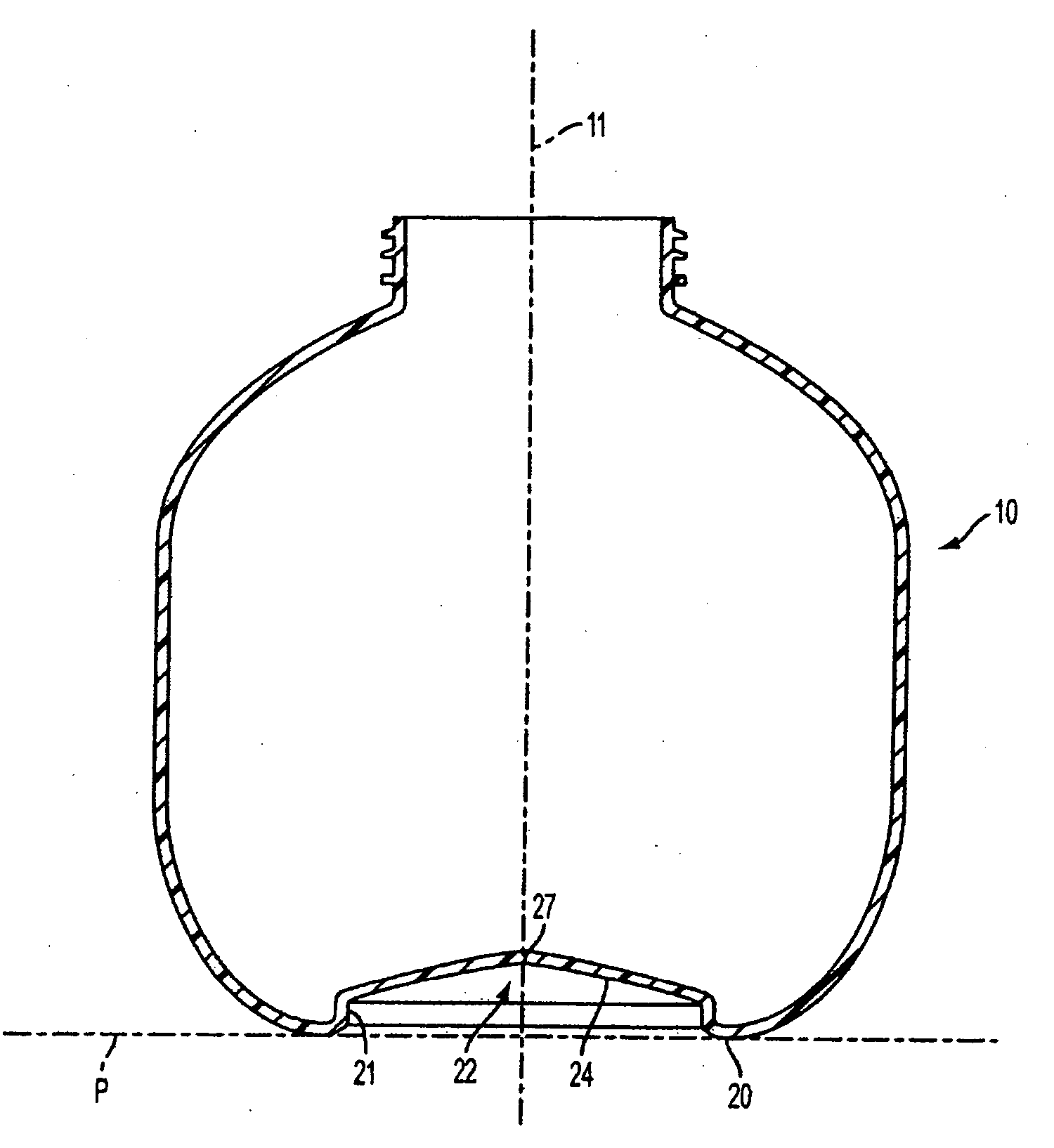
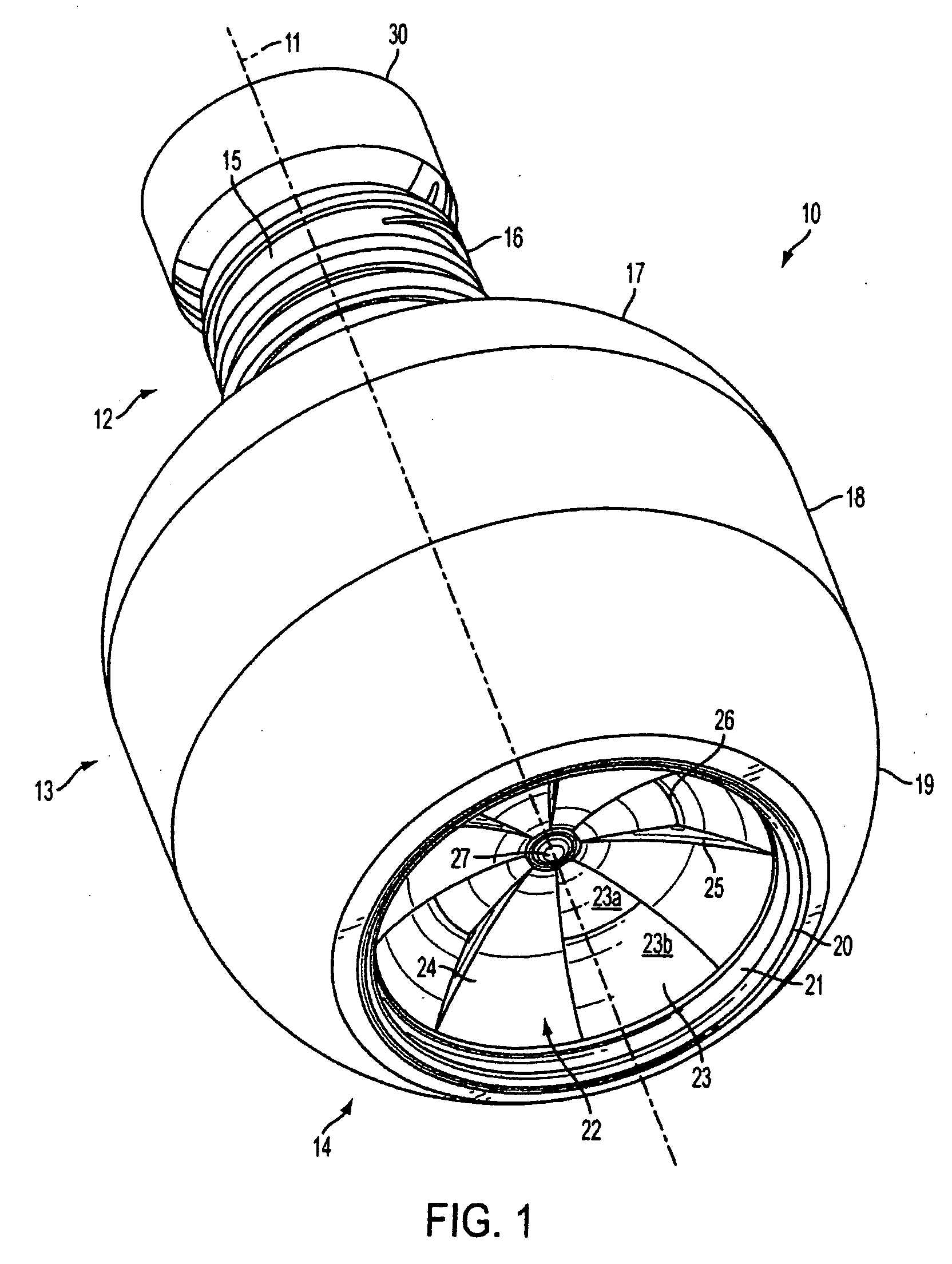
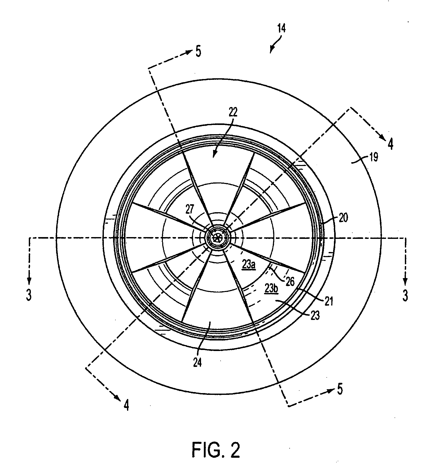
[0031]FIGS. 1 and 2 are perspective and bottom views, respectively, of a plastic container 10 according to an exemplary embodiment of the present invention. The container 10 is generally symmetrical around a longitudinal axis 11 and includes a neck portion 12, a body portion 13, and a base portion 14, together forming a substantially enclose...


PUM


Abstract

A base for a plastic container defining a central longitudinal axis. The base includes an annular standing ring portion defining a standing surface. The base includes a substantially cylindrical ring portion extending in a direction substantially perpendicular to the standing surface. The base further includes a substantially concave dome portion extending inwardly from the substantially cylindrical ring portion to the longitudinal axis. The concave dome portion of the base includes a first plurality of substantially triangular panels circumferentially spaced around the longitudinal axis, and a second plurality of substantially triangular panels circumferentially spaced around the longitudinal axis. At least a portion of each of the second plurality of substantially triangular panels is circumferentially and longitudinally offset from the first plurality of substantially triangular panels. A container preform and method of hot filling a plastic container are also disclosed.

Description

CROSS REFERENCE TO RELATED APPLICATIONS [0001] This Application claims the priority of U.S. Design application Ser. No. 29 / 242,551, filed Nov. 14, 2005, the entire contents of which are incorporated herein by reference.BACKGROUND OF THE INVENTION [0002] 1. Field of the Invention [0003] The present invention relates generally to a plastic container, and more particularly to a plastic container having a base structure that enhances the structural integrity of the container. The present invention also relates to a preform for forming a plastic container having a base structure that enhances the structural integrity of the container and a method for hot filling a plastic container with a product. [0004] 2. Related Art [0005] Plastic containers are commonly used to package a wide variety of liquid, viscous or solid products including, for example, juices, other beverages, yogurt, sauces, pudding, lotions, soaps in liquid or gel form, and candy. Such containers can be made by conventional...

Claims


Application Information

Patent Timeline
Patent Type & Authority Applications(United States)
IPC IPC(8): B65D90/12
CPCB67C3/045B65D1/0276
Inventor SIMPSON, CHARLES P. JR.BUDDEN, TODDDINKEL, JOHN PHILIP
Owner GRAHAM PACKAGING CO LP
Why Eureka
Try Eureka