Apparatus and method for sensing load of electric cooker

Active Publication Date: 2007-06-07
LG ELECTRONICS INC
View PDF3 Cites 71 Cited by
  • Summary
  • Abstract
  • Description
  • Claims
  • Application Information

AI Technical Summary

Benefits of technology

[0024] A still further object of the present invention is to provide an apparatus and method for sensing load of an electric cooker capable of operating

Problems solved by technology

However, only a cooking vessel made of a magnetic substance containing iron ingredients can be used for Joule heat to be generated in the resistance portion of the cocking vessel by the eddy current.
In other words, a cooking vessel made of a non-magnetic substance such as ceramics, glass or porcelain cannot be employed because the Joule heat is not generated therein.
However, an induction heating coil of an electric cooker capable of heating the cooking vessels made of magnetic and non-magnetic substances alike has a complicated structure as compared with that of the electric cooker capable of heating only the cooking vessel made of a magnetic substance.
Further, in the electric cooker capable of heating the cooking vessels made of magnetic and non-magnetic substances, an inverter for supplying high frequency current to the induction heating coil has a complicated structure to increase subsequent economic costs.
The induction heating electric cooker can be used to heat a cooking vessel made of a metallic

Method used


Image

  • Apparatus and method for sensing load of electric cooker
  • Apparatus and method for sensing load of electric cooker
  • Apparatus and method for sensing load of electric cooker

Examples


Embodiment Construction

[0037] Hereinafter, a preferred embodiment of a load sensing apparatus and method of the present invention will be described in detail with reference to the accompanying drawings. If it is determined that detailed descriptions on functions and constructions well known to those skilled in the art may make the scope of the present invention obscure, they will be omitted herfrom.

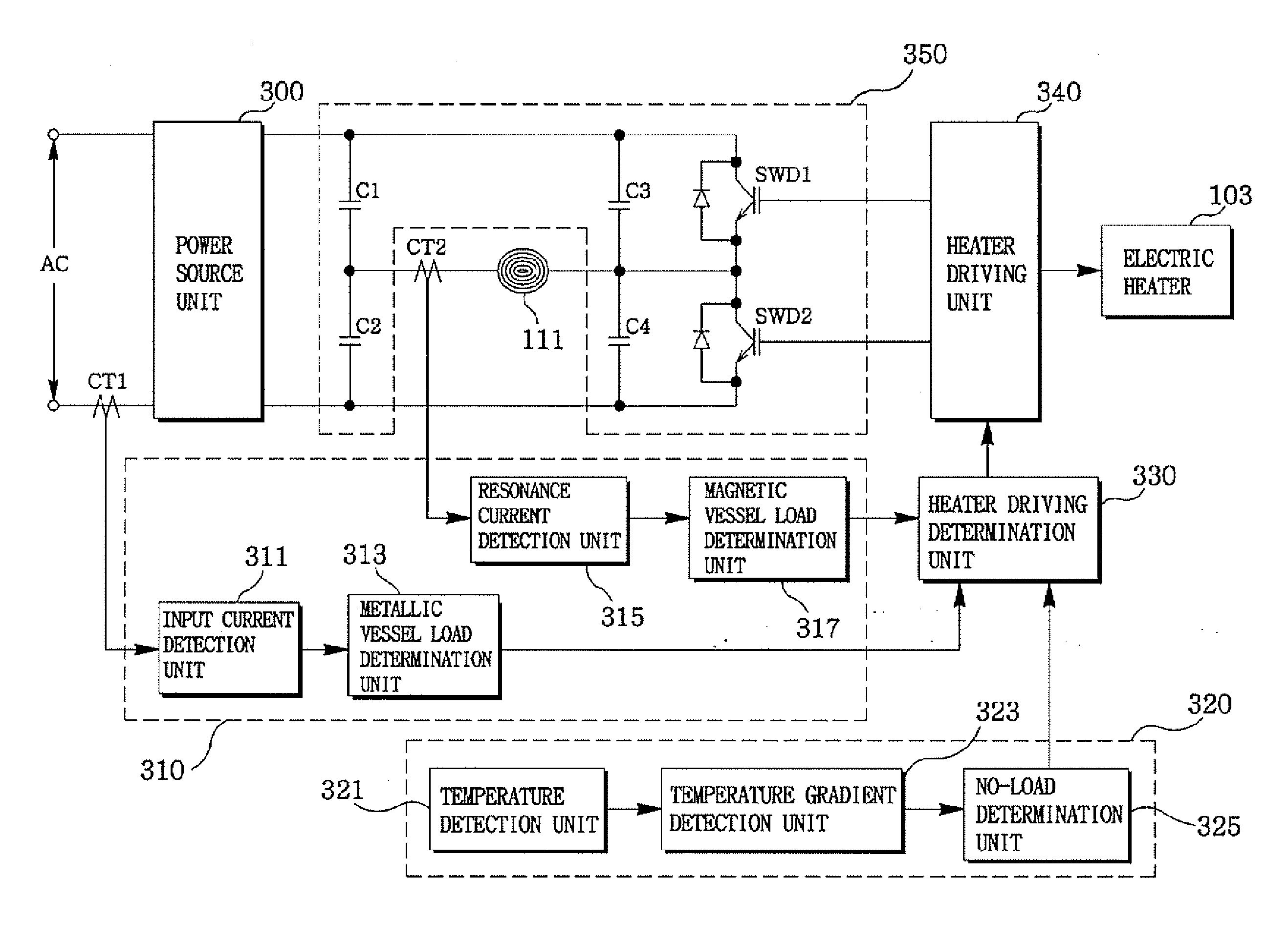
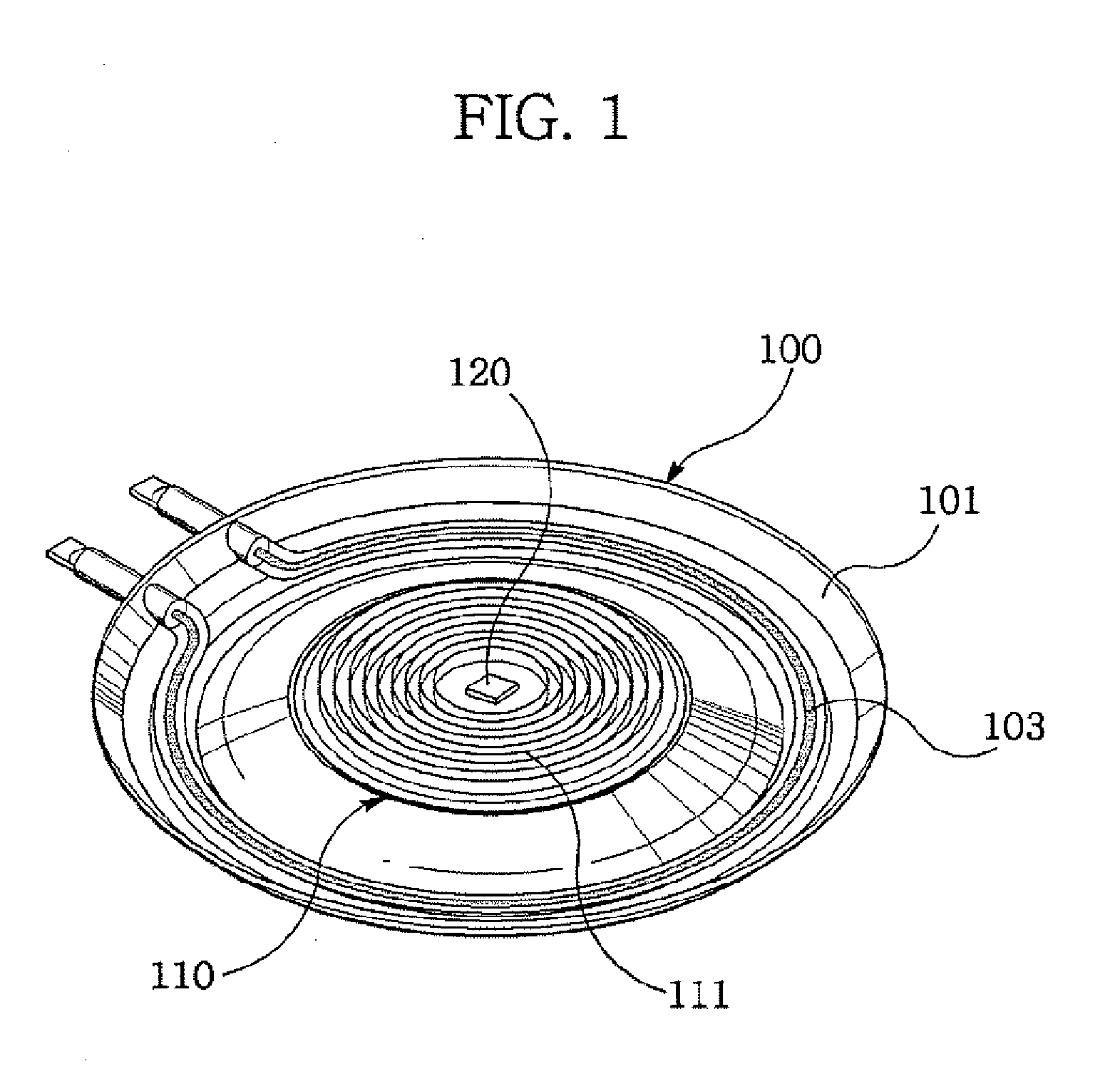
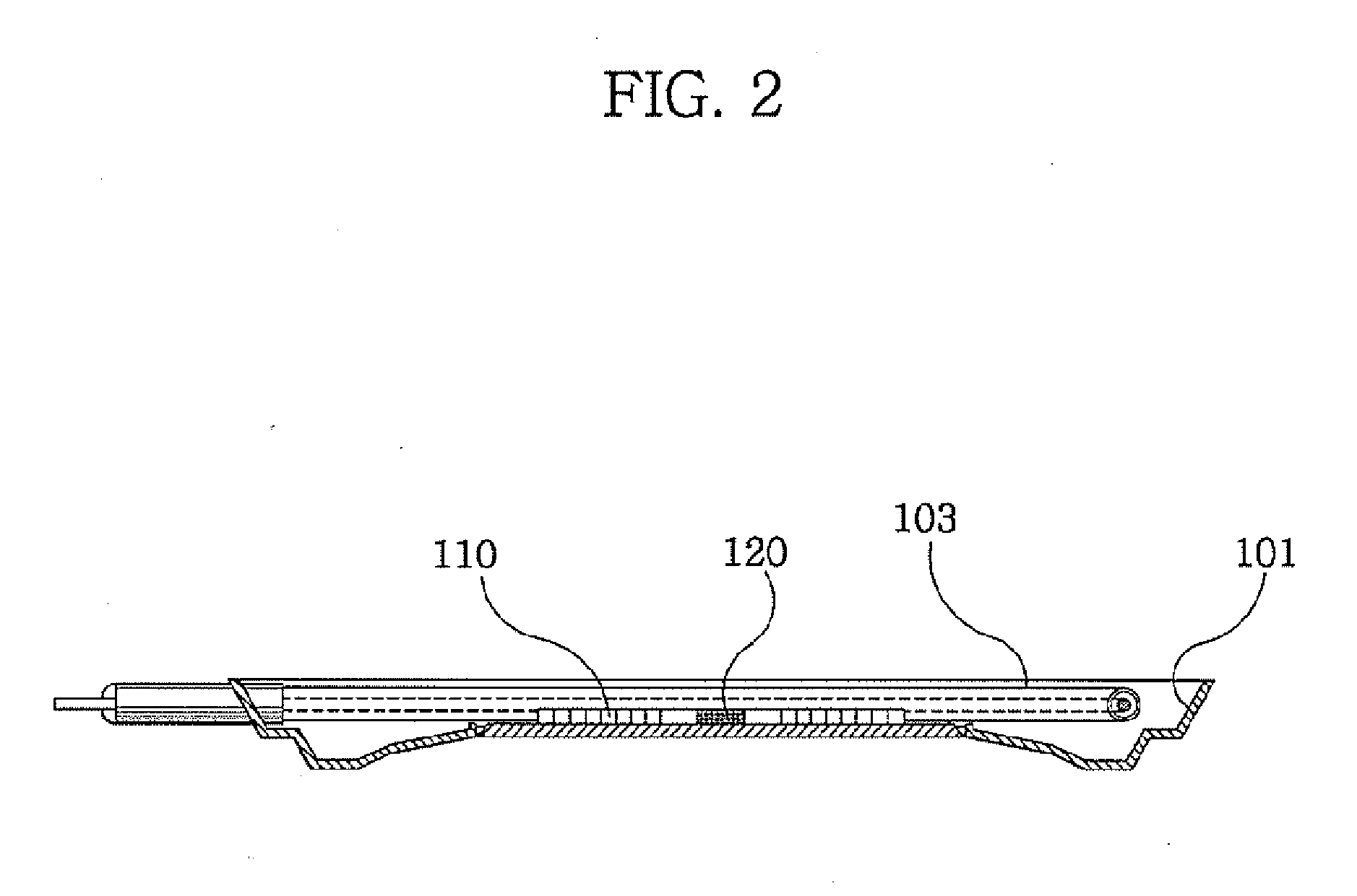
[0038]FIGS. 1 and 2 are perspective and enlarged sectional views showing the configuration of a heater unit used in a load sensing apparatus of the present invention, respectively. Referring to FIGS. 1 and 2, the heater unit of the present invention comprises an electric heating portion (100) and an induction heating portion (110).

[0039] The electric heating portion (100) includes a reflection plate (101) and an electric heater (103). The reflection plate (101) reflects radiant energy generated from the electric heater (103) to a cooking vessel (not shown in the figures) placed on the top of the heater unit t...


PUM


Abstract

A heater unit is provided, the heater unit equipped with an induction heating coil and an electric heater selectively operated based on kind and state of a load of a cooking vessel placed on the heater unit. The kind is determined by an input current inputted when a load-type determination unit causes the induction heating coil to be operated and a resonance current flowing into the induction heating coil. The state is determined by a temperature change of the heater unit when a load-state determination unit allows the electric heater to generate heat, and the induction heating coil and the electric heater are selectively operated based on the determined kind and state of the load. Accordingly, a user needs not to scrupulously determine the kind of the cooking vessel and the electric cooker is not operated under a no-load state to prevent occurrence of safety accidents.

Description

CROSS-REFERENCE TO RELATED APPLICATIONS [0001] This application claims priority under 35 U.S.C. §119 to Korean Patent Application No. 10-2005-0116807, filed on Dec. 2, 2005, the entirety of which is hereby incorporated by reference. BACKGROUND OF THE INVENTION [0002] This description relates to an apparatus and method for sensing load of an electric cooker. [0003] In general, a cooker generates heat by using an electric heater or by burning fuels such as liquefied petroleum gas (LPG) or liquefied natural gas (LNG). Further, a cooking vessel is heated by the generated heat to thereby cook a predetermined type of food. [0004] Although there are many kinds of cookers, an electric cooker capable of generating heat using electricity and cooking food thereby is very convenient and thus tends to be widely used. [0005] In particular, studies on high output and high efficiency induction heating used as a major heat source of an electric cooker such as a hob or a cook top have been actively c...

Claims


Application Information

Patent Timeline
IPC IPC(8): H05B6/12
CPCH05B6/062H05B2213/05H05B6/06
Inventor KIM, EUI SUNGRYU, SEUNG HEEOH, DOO YONGPARK, BYEONG WOOK
Owner LG ELECTRONICS INC
Why Eureka
Try Eureka