Control device for mobile body

a control device and mobile robot technology, applied in the direction of electric programme control, program control, instruments, etc., can solve the problems of unstable contact condition of the portion coming into contact, inability to control external forces acting on the knees, floor reaction forces, etc., and achieve the effect of stabilizing the posture of the robo

Active Publication Date: 2007-06-07
HONDA MOTOR CO LTD
View PDF4 Cites 52 Cited by
  • Summary
  • Abstract
  • Description
  • Claims
  • Application Information

AI Technical Summary

Benefits of technology

[0013] According to the first invention, the predetermined portion comes in contact with an external in the specific motion posture. This predetermined portion is the portion provided on the specific link mechanism at between the base body and the distal portion of the specific link mechanism, an external force acting on the predetermined portion being detected or estimated by the external force detecting means. Then, the displacement of the joint existing at least between the predetermined portion and the base body is controlled such that the detected or estimated external force approximates a desired external force determined by the desired external force determining means, making it possible to properly control the external force acting on the predetermined portion. As a result, the stability of a posture of the robot can be maintained.
[0015] Further, in the aforesaid first invention (or the first and the second inventions), the specific link mechanisms, for example, are leg bodies extended from buttocks connected to the base body through the intermediary of joints, and the predetermined portion is the buttocks (a third invention). In this case, when a robot is sitting or the like, the external force acting on the buttocks can be controlled so as to control the posture of the robot (particularly the posture of the base body, such as the body) to a proper stable posture.
[0017] According to the fourth invention, the external force acting on the predetermined portion can be controlled so as to restore the actual posture of the second predetermined portion (e.g., the base body) to a predetermined desired posture, thus allowing the stability of a posture of the robot to be enhanced.
[0019] According to the fifth invention, the displacement of a joint is controlled such that the external force acting on the predetermined portion approximates a desired external force and also the actual posture of the second predetermined portion (e.g., the base body) approximates a desired posture, thus making it possible to stabilize a posture of the robot and also to properly control an external force acting on a predetermined portion.

Problems solved by technology

Hence, it has been impossible to control external forces (e.g., floor reaction forces) acting on the knees.
For this reason, there have been cases where a projection or a depression causes a portion of the robot that comes into contact with a floor shakes, resulting in unstable contact condition of the portion coming into contact.
Under this condition, an attempt to make the robot operate or work has sometimes led to an unstable posture of the robot.
Furthermore, when, for example, a robot stands up from a kneeling posture, if the actual inclination of a floor is different from the inclination assumed in a desired gait, then there has been a danger in that the robot falls, because the position of the center-of-gravity of the robot is not properly controlled and the robot undesirably tries to stand up with its body posture inclined.

Method used


Image

  • Control device for mobile body
  • Control device for mobile body
  • Control device for mobile body

Examples


first reference example

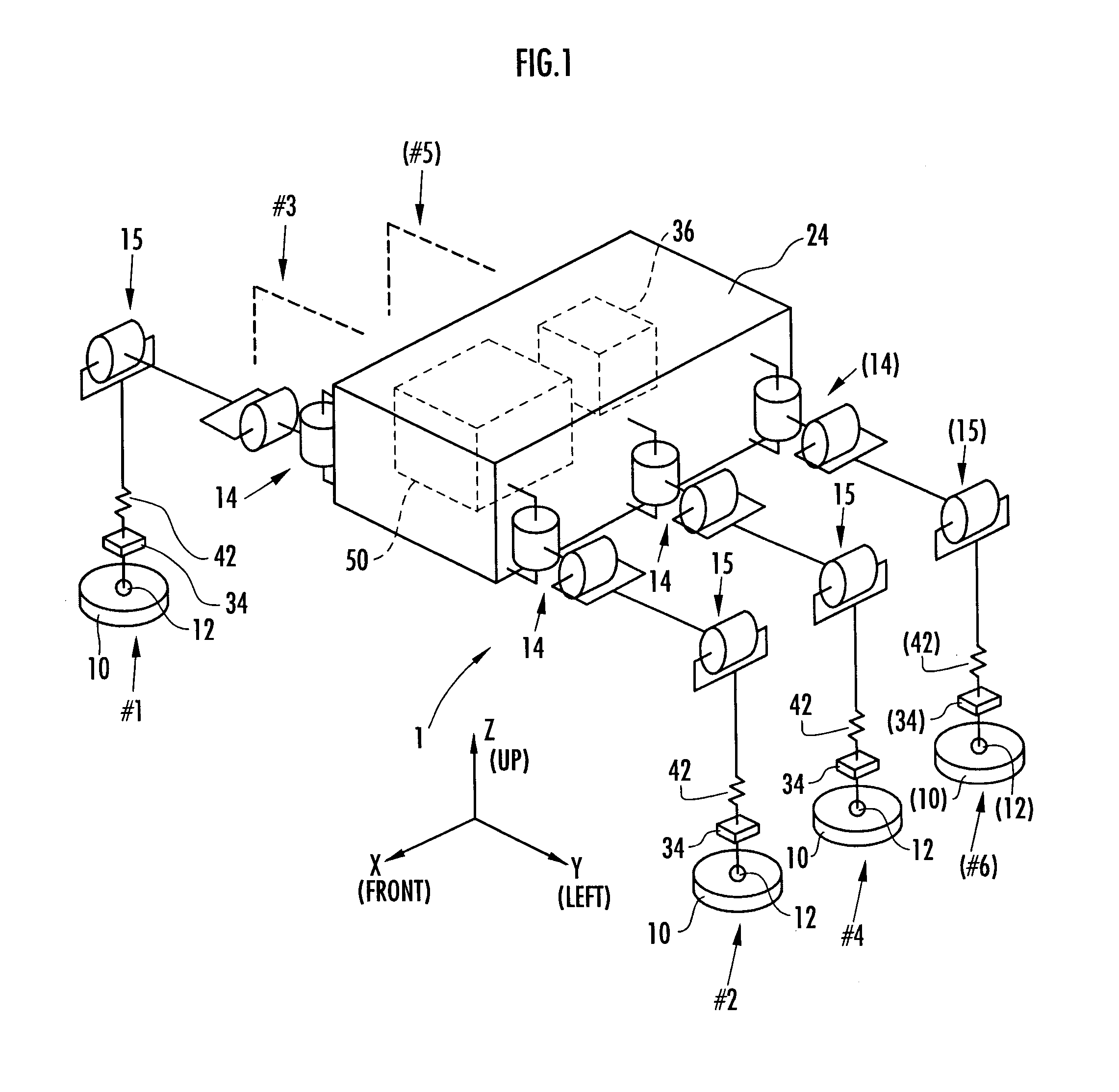
[0078]FIG. 1 is an external view of a general multi-legged mobile robot (legged mobile robot) according to first and second reference examples. FIG. 1 shows that the robot 1 has six legs (leg bodies), namely, a first leg #1 to a sixth leg #6; however, it does not have the fifth leg #5 and the sixth leg #6 in the first reference example. This means that, in the first reference example, the robot 1 is a four-legged robot having four legs (leg bodies), the first leg #1 to the fourth leg #4. In FIG. 1, the components of the robot 1 according to the second reference example are shown by parenthesized reference numerals.

[0079] As shown in FIG. 1, in the robot 1 (the four-legged robot) according to the first reference example, two legs (the first leg #1 and the third leg #3) are extended from the right side of a body 24, which is the base body of the robot 1, such that they are arranged side by side in the longitudinal direction, and in the same manner, two legs (the second leg #2 and the...

second reference example

[0280] The following will explain a second reference example of the present invention with reference to the aforesaid FIG. 1 and FIG. 24 to FIG. 34. Referring to FIG. 1, the explanation will be focused on the aspects of a robot 1 of the second reference example that are different from the robot of the first reference example. The robot 1 of the second reference example is provided with, in addition to the first to the fourth legs #1 to #4, a fifth leg #5 and a sixth leg #6 having the same structures as those of the legs #1 to #4. This means that the robot 1 of the second reference example is a six-legged robot. The fifth leg #5 is behind the third leg #3 and extended from the right side of the body 24 of the robot 1, and the sixth leg #6 is behind the fourth leg #4 and extended from the left side of the body 24 of the robot 1. The rest of the mechanical structure of the robot 1 is the same as that of the first reference example, so that the like reference numerals as those of the fi...

third reference example

[0339] An explanation will now be given of a third reference example in which a floor configuration estimating function and a function for correcting the operation of the robot 1 on the basis of the result of the estimation have been added to the robot 1 (six-legged robot) of the second reference example. In the present reference example, the explanation will be focused mainly on the six-legged robot shown in the second reference example; however, supplemental explanation will be added also to a four-legged robot in some cases. In addition, for the convenience of the understanding of the present reference example, a two-legged robot will be also referred to in some cases.

[0340] The mechanical construction of the robot 1 in the present reference example is the same as that shown in FIG. 1 explained in the first or the second reference example (except that the robot 1 has six legs #1 to #6). Hence, the explanation of the mechanical construction of the robot 1 will be omitted. The fun...


PUM


Abstract

A control system for a mobile robot is provided with a base body 53 and a plurality of link mechanisms 52 and 54 connected thereto. A sensor 90 for detecting external forces is provided on a predetermined portion (knee) between the base body 53 and a distal portion (foot) 58 of the link mechanism (leg) 52. In a motion posture in which a robot 61 has a predetermined portion (knee) in contact with the ground, the displacement of at least a joint 55 between the base body 53 and the predetermined portion (knee) is controlled so as to bring an external force (floor reaction force) detected by the sensor 90 close to a desired external force. In a state wherein a portion other than a distal portion of a leg or arm of the robot 61 is in contact with a floor or the like and subject to an external force, the external force acting on the portion other than the distal portion of the leg or arm is properly controlled, thereby maintaining a stable posture of the robot 61.

Description

TECHNICAL FIELD [0001] The present invention relates to a control system for a mobile robot, such as a bipedal mobile robot and, more specifically, to a system for controlling a floor reaction force (external force) acting on the mobile robot in a case where a portion of the robot, such as a knee, an elbow, or a trunk, other than a distal portion of a leg or an arm of the robot is brought into contact with the ground or in a similar case. BACKGROUND ART [0002] As the technologies for controlling the floor reaction force acting on the distal portions of the legs of a legged mobile robot, such as a bipedal mobile robot, when making the robot travel by causing the distal portions of its legs to come in contact with or leave a floor, there have been known the technologies disclosed in Japanese Unexamined Patent Application Publication No. H5-305585 (Patent Document 1), Japanese Unexamined Patent Application Publication No. H10-277969 (Patent Document 2) and Japanese Unexamined Patent Ap...

Claims


Application Information

Patent Timeline
Patent Type & Authority Applications(United States)
IPC IPC(8): G05B19/04B25J5/00B25J13/00B62D57/032
CPCB25J13/085B62D57/032B25J5/00B25J13/00
Inventor TAKENAKA, TORUMATSUMOTO, TAKASHIYOSHIIKE, TAKAHIDE
Owner HONDA MOTOR CO LTD
Why Eureka
Try Eureka