Display module and electronic device using the same

a technology applied in the field of display modules and electronic devices using the same, can solve problems such as inability to solve problems, increase manufacturing costs, and take development time, and achieve the effects of low cost, low manufacturing cost, and high quality appearan

Inactive Publication Date: 2007-06-07
SEMICON ENERGY LAB CO LTD
View PDF16 Cites 19 Cited by
  • Summary
  • Abstract
  • Description
  • Claims
  • Application Information

AI Technical Summary

Benefits of technology

[0018] In accordance with the present invention, a stacked printed circuit board can be used in common for display panels with different specifications in a display module, and development costs or manufacturing costs of the display module can be reduced. Furthermore, by providing a plurality of connecting edges for the stacked printed circuit board, and making a controller, which can change the function and configuration of a logic circuit, be able to select where to output a signal, a connection structure with a display panel can be optimized in accordance with the size or mode of housing. Accordingly, the display module can be put in an electronic device compactly. Such effects offer flexibility in designing an electronic device and enable an electronic device with high quality appearance to be provided. In addition, through mounting of this kind of display module, an inexpensive and high-performance electronic device can be provided.

Problems solved by technology

That is, as for conventional display modules, even a slight change in design requires that the printed wiring board be designed from the beginning, which takes development time and leads to an increase in manufacturing costs.
This kind of problem cannot be solved by simply improving each of the parts.

Method used


Image

  • Display module and electronic device using the same
  • Display module and electronic device using the same
  • Display module and electronic device using the same

Examples


embodiment 1

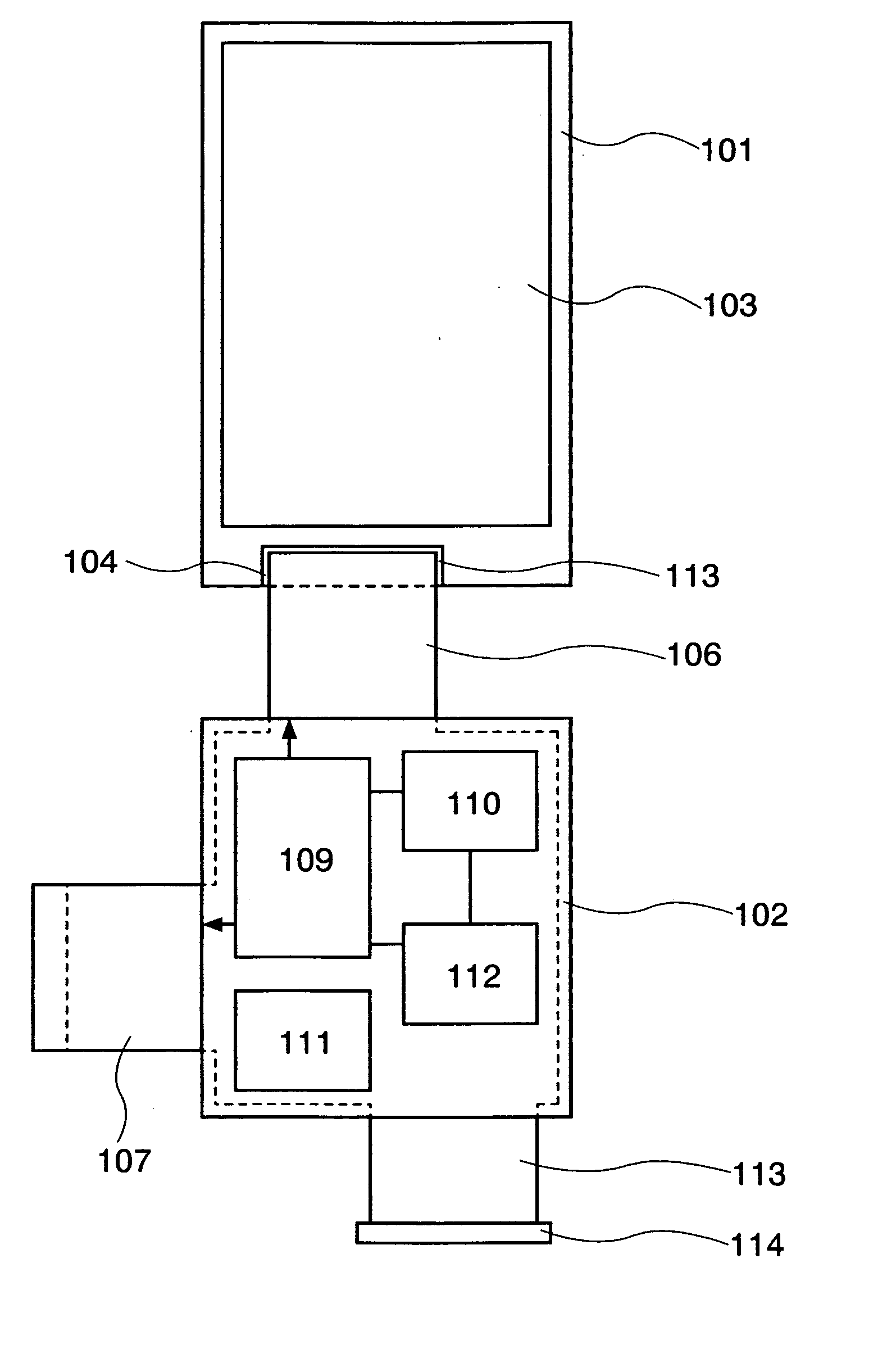
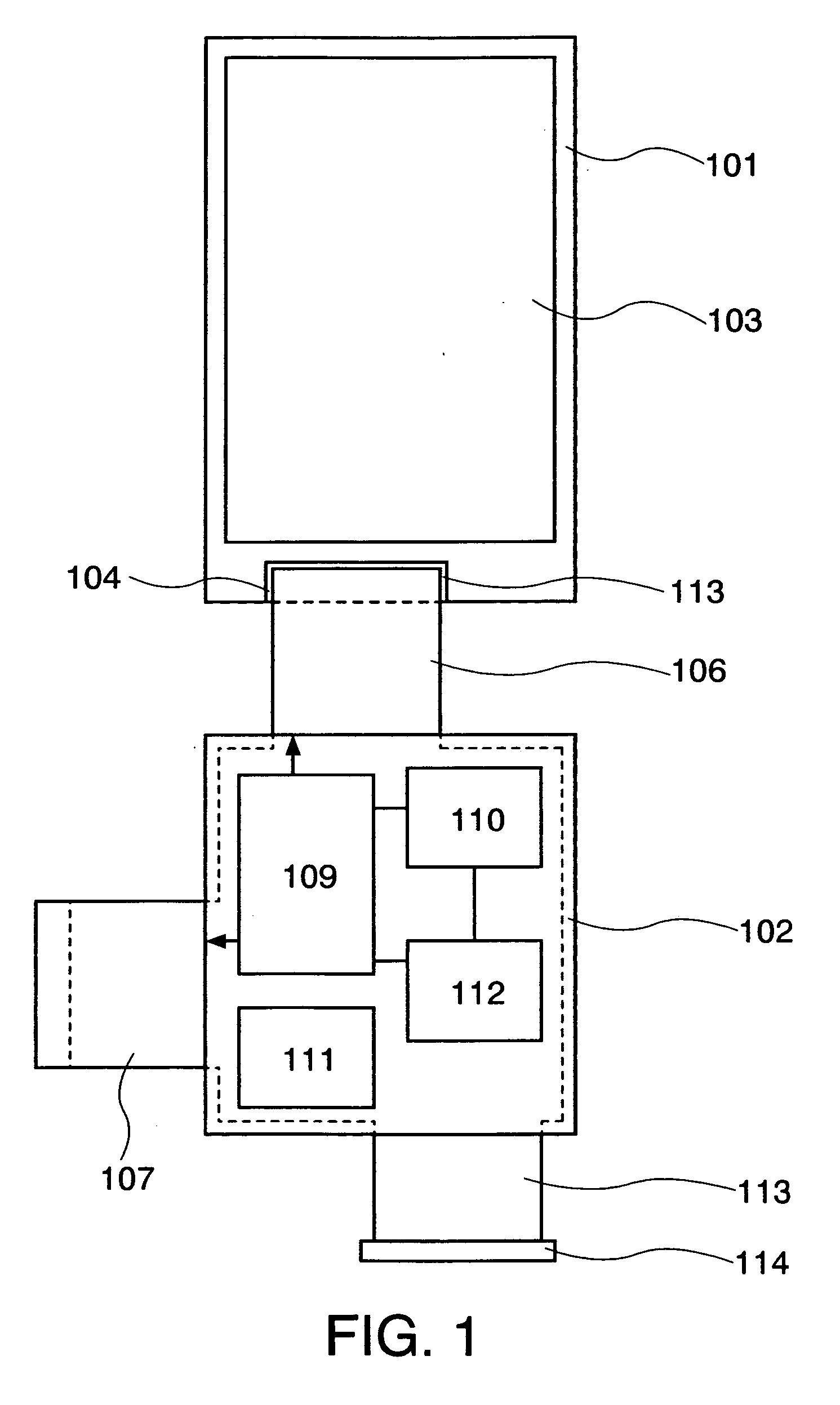
[0065] In this embodiment, a circuit configuration of the display module of the present invention which is described in Embodiment Mode will be explained with reference to FIG. 5. FIG. 5 is a circuit diagram for explaining in detail about a change in a logic circuit and input and output terminals of a controller, which is a characteristic portion of the display module of the present invention. It is to be noted that the same portions as in FIGS. 1 and 2 described in Embodiment Mode are denoted by the same reference numerals, and the repeated description will be omitted.

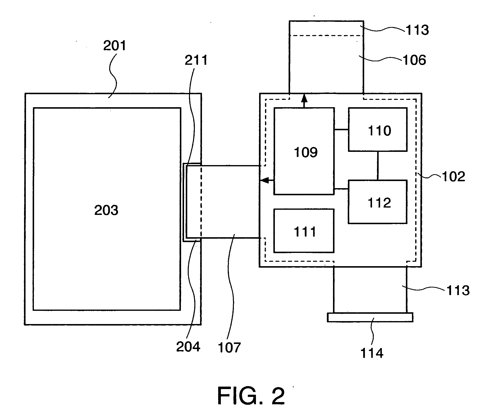
[0066] In FIG. 5, a controller 109 includes a logic circuit 506, a ROM 507, and first to 26th input and output terminals 511 to 536. A first connecting edge 106 is connected to a first display panel 101. The first connecting edge 106 is constituted by first to fifth connecting terminals 541 to 545. A second connecting edge 107 is connected to a second display panel 201. The second connecting edge 107 is constituted b...

embodiment 2

[0073] In this embodiment, an example of a circuit configuration of the display module of the present invention described in Embodiment Mode, which is different from the one described in Embodiment 1, will be described with reference to FIG. 6. FIG. 6 is a circuit diagram for explaining in detail about a change in a logic circuit and input and output terminals of a controller, which is a characteristic portion of the display module of the present invention. Further, 19th to 23rd input and output terminals 529 to 533 are not electrically connected to a connecting terminal. It is to be noted that the same portions as in FIGS. 1 and 2 described in Embodiment Mode and FIG. 5 described in Embodiment 1 are denoted by the same reference numerals, and the repeated description will be omitted.

[0074] It is to be noted that the data stored in the ROM 507 is information that 19th to 23rd input and output terminals 529 to 533 are not electrically connected to a connecting terminal. It is to be ...

embodiment 3

[0079] In this embodiment, an example of a circuit configuration of the display module of the present invention described in Embodiment Mode, which is different from the ones described in Embodiments 1 and 2, will be described with reference to FIG. 7. FIG. 7 is a circuit diagram for explaining in detail about a change in a logic circuit and input and output terminals of a controller, which is a characteristic portion of the display module of the present invention. It is to be noted that the same portions as in FIGS. 1 and 2 described in Embodiment Mode, FIG. 5 described in Embodiment 1, and FIG. 6 described in Embodiment 2 are denoted by the same reference numerals, and the repeated description will be omitted.

[0080] In FIG. 7, 14th to 16th input and output terminals 524 to 526 are electrically connected to first to third connecting terminals 541 to 543, respectively. Nineteenth to 21st input and output terminals 529 to 531 are electrically connected to sixth to eighth connecting ...


PUM


Abstract

A display module is provided, which comprises a stacked printed circuit board, and a control circuit mounted on the stacked printed circuit board. The stacked printed circuit board includes at least a first printed wiring board, a second printed wiring board, and a flexible insulating substrate interposed between the first printed wiring board and the second printed wiring board. The flexible insulating substrate includes at least a first connecting portion and a second connecting portion. A display panel is electrically connected to one of the first connecting portion and the second connecting portion. The control circuit includes a memory. The control circuit supplies an electrical signal to the one of the first connecting portion and the second connecting portion in accordance with a data stored in the memory.

Description

TECHNICAL FIELD [0001] The present invention relates to a display module and an electronic device using the display module. In particular, the present invention relates to a display module having a display panel including a TFT using a semiconductor thin film as an active layer, and an electronic device using such a display module. BACKGROUND ART [0002] In recent years, research and development on a display panel, including a TFT (thin film transistor) that has a polycrystalline silicon thin film as an active layer, as a switching element in a pixel portion or an active matrix display panel in which circuits for driving pixels are formed in a periphery of a pixel portion has been actively carried out. [0003] The biggest advantages of a display panel having a polycrystalline silicon thin film as described above are as follows: it is thin; it is thin and light-weight and has low power consumption. Utilizing such advantages, the display panel having a polycrystalline silicon thin film ...

Claims


Application Information

Patent Timeline
Patent Type & Authority Applications(United States)
IPC IPC(8): G09G5/00
CPCG06F3/1431G09G2360/04G09G3/2096H05K3/4691G09G2360/18G09G3/20G09G3/30
Inventor KUROKAWA, YOSHIYUKI
Owner SEMICON ENERGY LAB CO LTD
Why Eureka
Try Eureka