Apparatus and method for synchronously stimulating a plurality of fluid jets

Inactive Publication Date: 2007-06-07
EASTMAN KODAK CO
View PDF9 Cites 17 Cited by
  • Summary
  • Abstract
  • Description
  • Claims
  • Application Information

AI Technical Summary

Benefits of technology

[0013] The above-described problems are addressed and a technical solution is achieved in the art by an apparatus and a method for synchronously stimulating a plurality of fluid jets according to the present invention. In an embodiment of the present invention a common electrohydrodynamic stimulation electrode is provided to synchronously stimulate all members of a plurality of conductive fluid jets to form a corresponding plurality of drop streams; The common electrohydrodynamic stimulation electrode includes a contiguous electrically conductive portion that forms at least a portion of each member of a plurality of nozzle channels, from which the fluid jets are emitted. The common electrohydr

Problems solved by technology

Failure to synchronize may result in partially charged drops that may deposit at incorrect positions on the recording surface 42 or gutter 40 which in turn, may adversely impact print quality and print-head reliability.
This synchronization problem is additionally compounded when the print head includes multip

Method used


Image

  • Apparatus and method for synchronously stimulating a plurality of fluid jets
  • Apparatus and method for synchronously stimulating a plurality of fluid jets
  • Apparatus and method for synchronously stimulating a plurality of fluid jets

Examples


Embodiment Construction

[0036] Throughout the following description specific details are presented to provide a more thorough understanding to persons skilled in the art. However, well-known elements may not have been shown or described in detail to avoid unnecessarily obscuring the disclosure. Accordingly, the description and drawings are to be regarded in an illustrative, rather than a restrictive, sense.

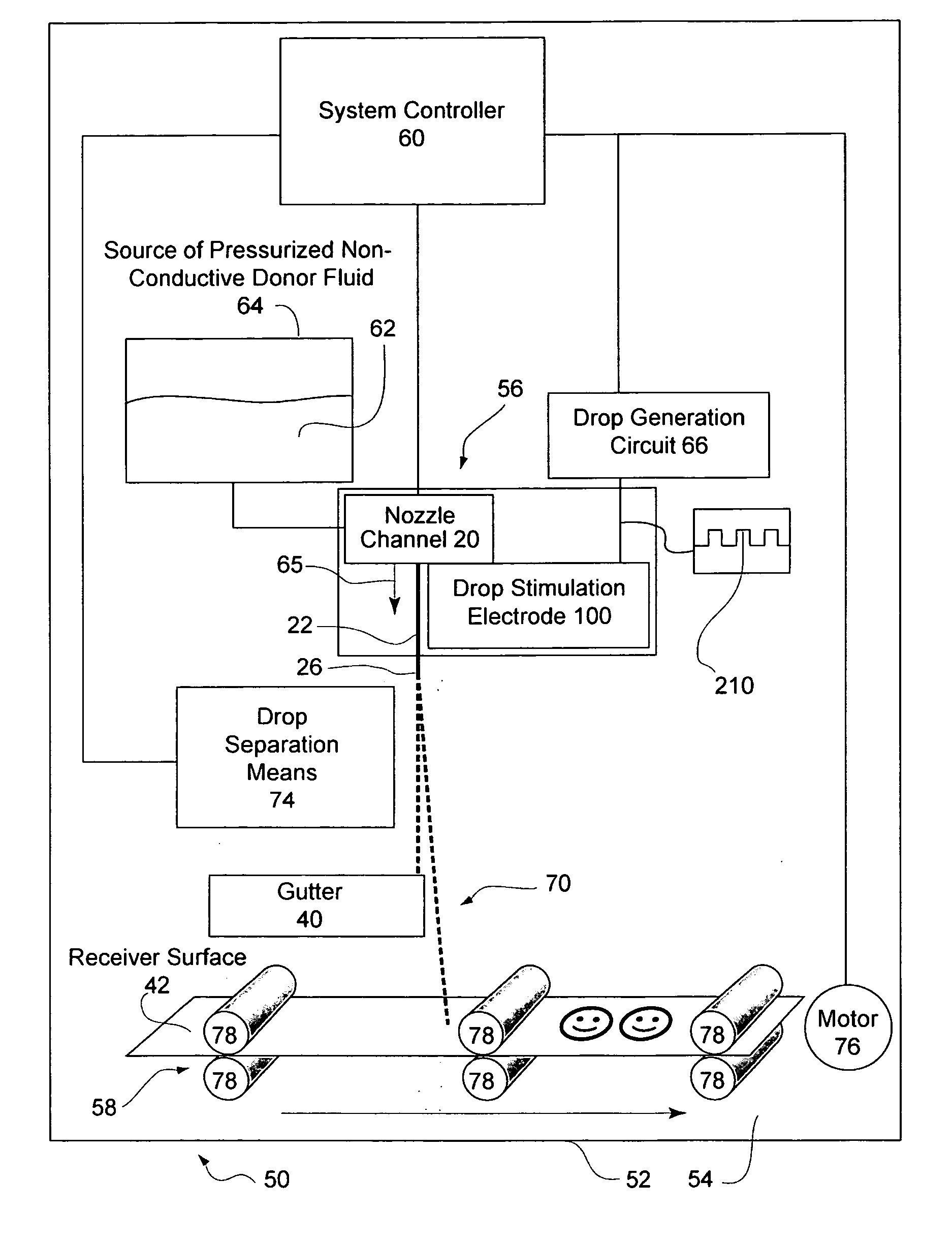
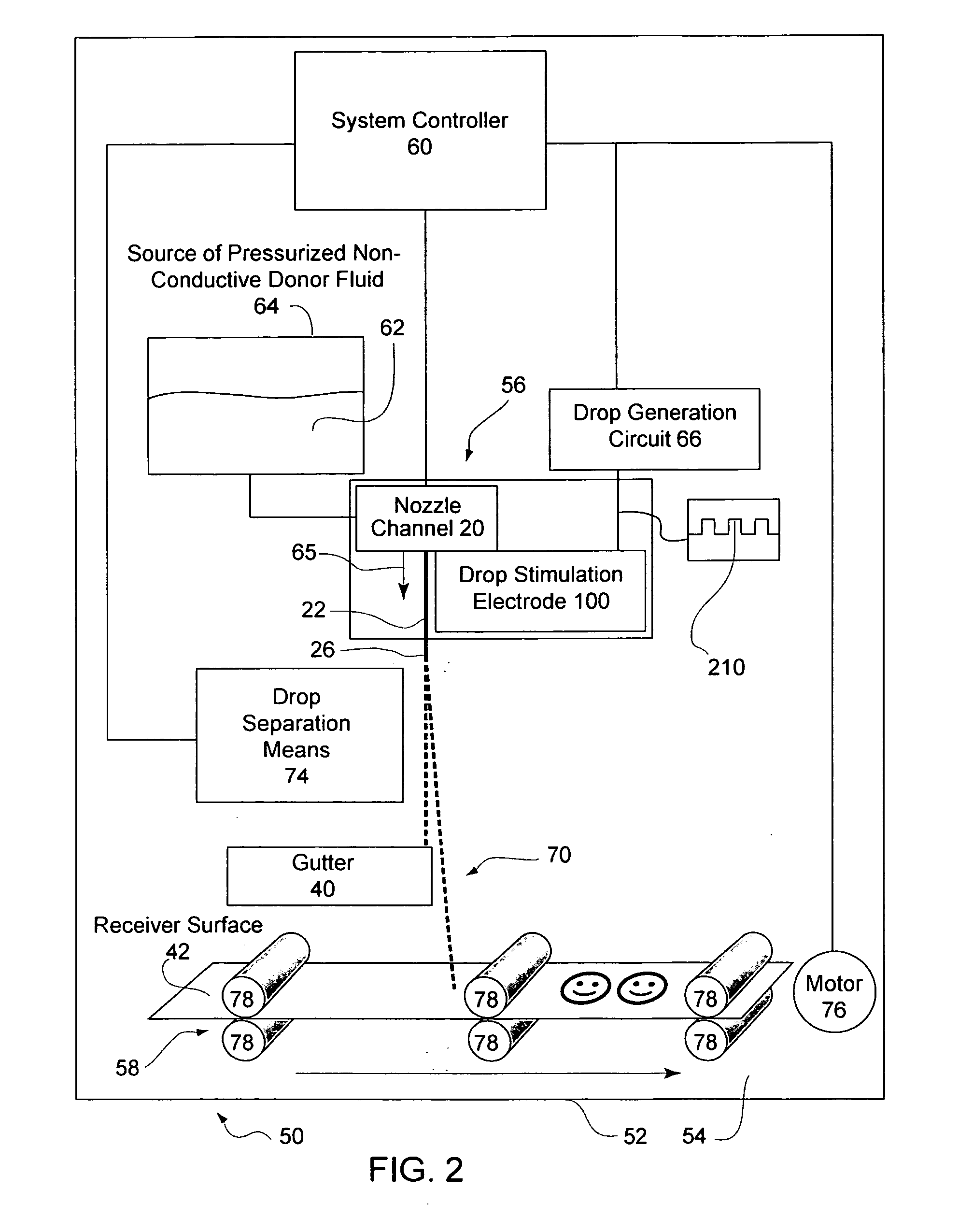
[0037]FIG. 2 schematically shows a printing apparatus 50, according to an embodiment of the present invention. Printing apparatus 50 includes a housing 52 that can include any of a box, closed frame, continuous surface or any other enclosure defining an interior chamber 54. In the embodiment of FIG. 2, interior chamber. 54 of housing 52 holds an inkjet print-head 56, a translation unit 58 that positions a receiver surface 42 relative to inkjet print-head 56, and system controller 60. System controller 60 may include a micro-computer, micro-processor, micro-controller or any other known arrangement of el...


PUM


Abstract

A common electrohydrodynamic stimulation electrode, in response to an electrical signal, synchronously stimulates all members of a group of fluid jets emitted from corresponding nozzle channels to form a corresponding plurality of continuous streams of drops. The common electrohydrodynamic stimulation electrode includes an electrical contact operable to transmit the electrical signal to each member of the nozzle channels via a contiguous electrically conductive portion. The contiguous electrically conductive portion forms a permanently electrically conductive path between and forms a portion of each nozzle channel. Synchronous stimulation of each of the fluid jets facilitates accurate phase locking of print data dependent charging of the drop streams.

Description

FIELD OF THE INVENTION [0001] The invention pertains to the field of ink jetting fluids and, in particular to simultaneously stimulating a plurality of fluid jets to form a corresponding plurality of streams of drops. BACKGROUND OF THE INVENTION [0002] The use of ink jet printers for printing information on a recording medium is well established. Printers employed for this purpose may be grouped into those that emit a continuous stream of fluid drops, and those that emit drops only when corresponding information is to be printed. The former group is generally known as continuous inkjet printers (CIJ) and the latter as drop-on-demand inkjet printers. The general principles of operation of both of these groups of printers are very well recorded. Drop-on-demand inkjet printers have become the predominant type of printer for use in home computing systems, whereas continuous inkjet systems find major application in industrial and professional environments. [0003] Continuous inkjet system...

Claims


Application Information

Patent Timeline
IPC IPC(8): B41J2/06
CPCB41J2/03B41J2/035B41J2/115
Inventor STEINER, THOMAS W.
Owner EASTMAN KODAK CO
Why Eureka
Try Eureka