Light emission method, light emitting apparatus and projection display apparatus

a technology of light emitting apparatus and projection display apparatus, which is applied in the direction of lighting and heating apparatus, static indicating devices, instruments, etc., can solve the problems of difficult to further increase the light amount in a state, high color reproducibility, and lighting over a period longer, and achieve the effect of increasing the light amoun

Active Publication Date: 2007-06-07
PANASONIC CORP
View PDF9 Cites 26 Cited by
  • Summary
  • Abstract
  • Description
  • Claims
  • Application Information

AI Technical Summary

Benefits of technology

[0066] According to the present invention, in a light source emitting single-color light represented by a solid li

Problems solved by technology

In addition, the light emitting diode can emit single-color light, and therefore it is unnecessary to take the trouble to chromatically separate emitted light.
On the other hand, there is a problem as described below.
Thus, the maximum light intensity of the green light emitting diode 1(b) restricts the light intensities of all the light emitting diodes, and it is difficult to further increase the light amount in a state in which

Method used


Image

  • Light emission method, light emitting apparatus and projection display apparatus
  • Light emission method, light emitting apparatus and projection display apparatus
  • Light emission method, light emitting apparatus and projection display apparatus

Examples


embodiments

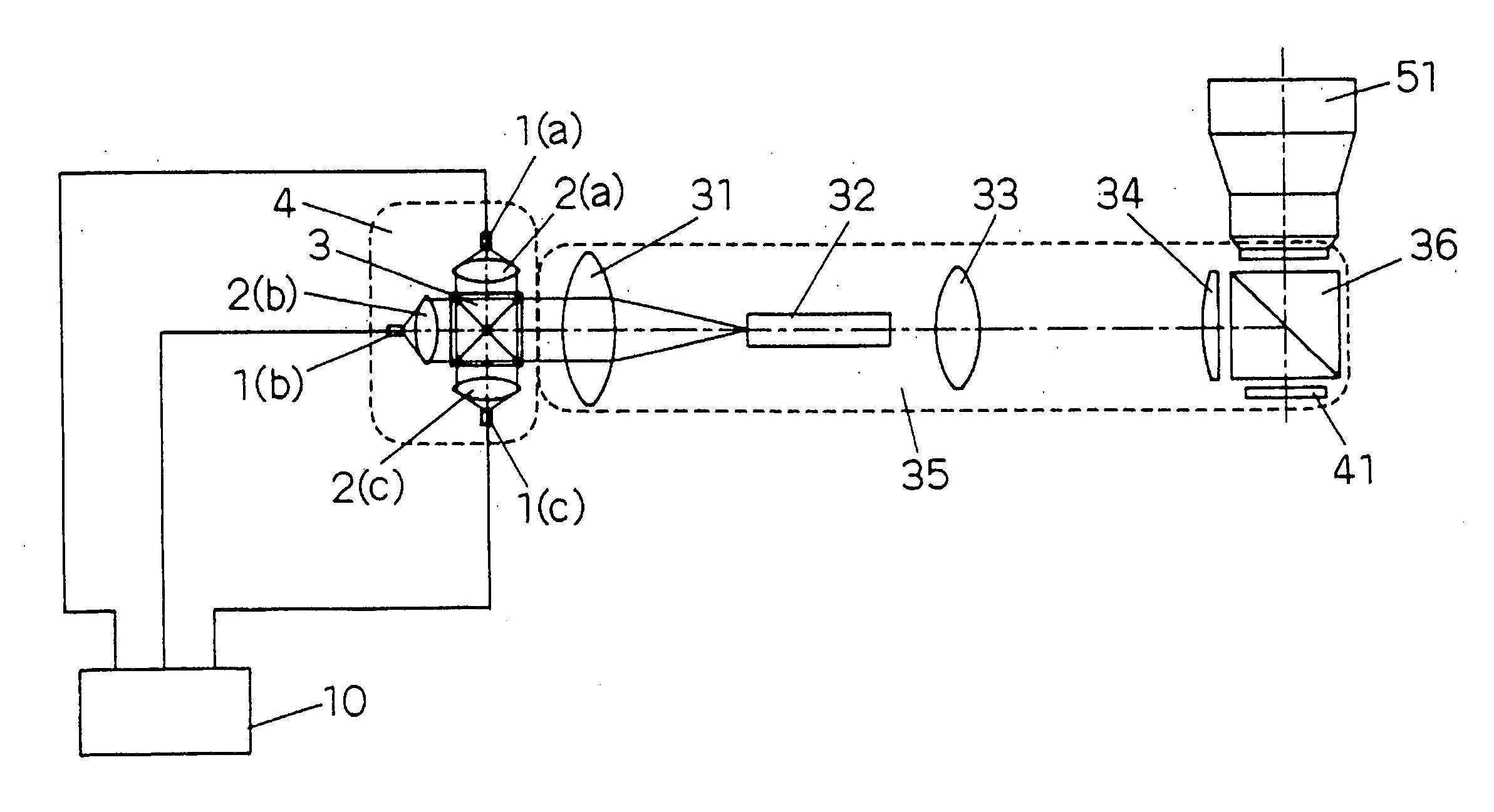
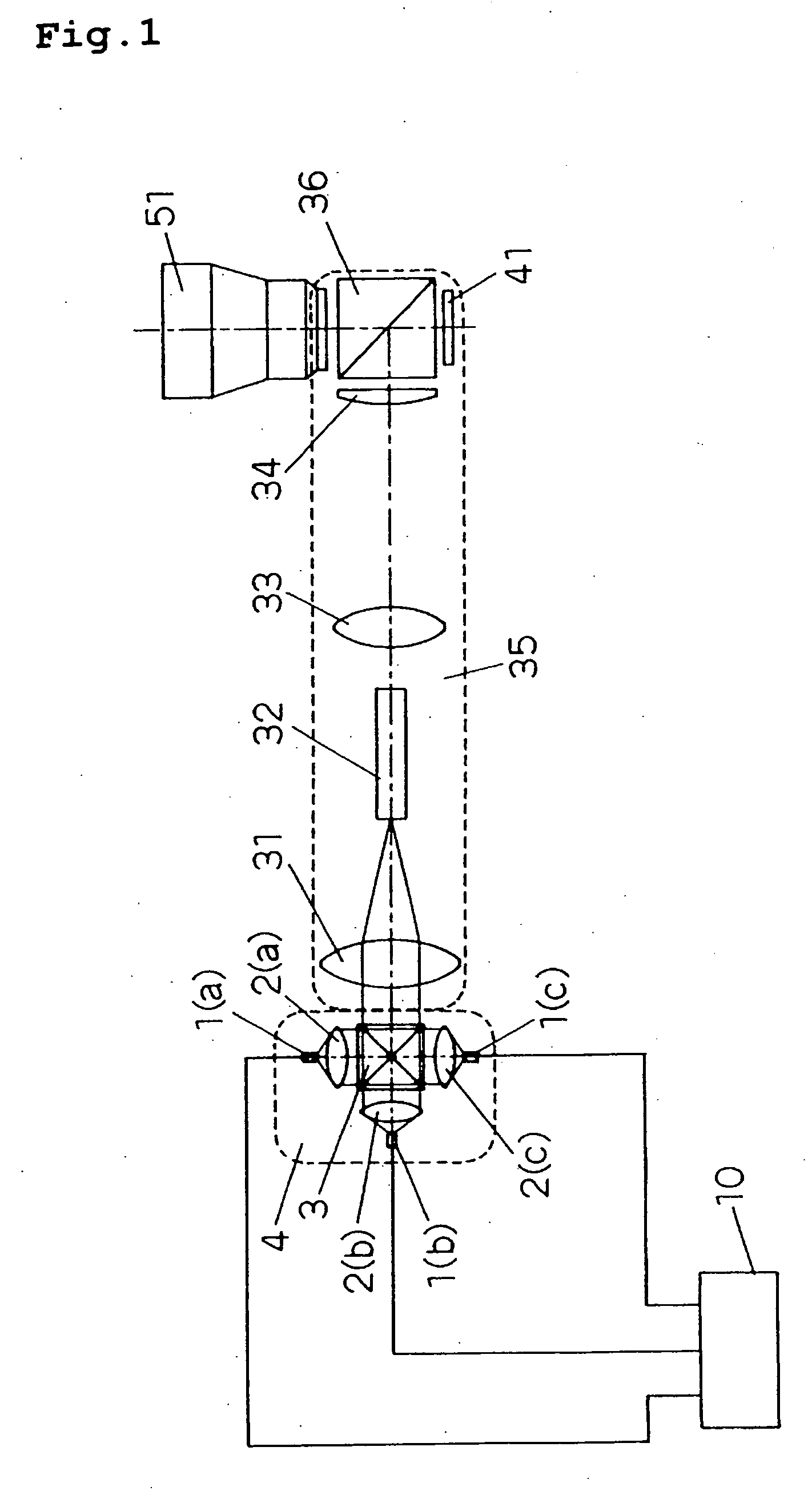
[0104] An outlined configuration of a projection display apparatus according to the embodiment of the present invention is shown in FIG. 1.

[0105] The apparatus of FIG. 1 is comprised of a light source unit 4 comprising a red light emitting diode 1(a) as a red light source and a lens for red light 2(a) of collecting light fluxes emitted from the red light emitting diode 1(a), a green light emitting diode 1(b) as a green light source and a lens for green light 2(b) of collecting light fluxes emitted from the green light emitting diode 1(b), a blue light emitting diode 1(c) as a blue light source and a lens for blue light 2(c) of collecting light fluxes emitted from the blue light emitting diode 1(c), a cross prism 3 of synthesizing the light fluxes emitted from the light emitting diodes 1(a), 1(b) and 1(c), and a control instrument 10 controlling the lighting period and the light intensity during lighting for each of the red light emitting diode 1(a), the green light emitting diode 1...


PUM


Abstract

In a light source emitting single-color light represented by a solid light source such as a light emitting diode, a light output is increased while a color reproducibility is maintained. A red, a green, and a blue light emitting diode are controlled so that a first light emitting step of making the red light emitting diode emit light in a first light emission period, a second light emitting step of making the green light emitting diode emit light in a second light emission period, a third light emitting step of making the blue light emitting diode emit light in a third light emission period, and a fourth light emitting step of making the red light emitting diode, the green light emitting diode and the blue light emitting diode emit light at the same time in a fourth light emission period are carried out for display of one image.

Description

[0001] This application is a U.S. national phase application of PCT International Application PCT / JP2005 / 001138, filed Jan. 27, 2005. TECHNICAL FIELD [0002] The present invention relates to a light emission method of a light source, a light emitting apparatus and the like, which are used in a projection display apparatus of projecting a large size image onto a screen using a light generating instrument as a light source, a light modulation element, a projection lens as a projection instrument, and the like. BACKGROUND ART [0003] In recent years, projection display apparatuses (projectors) using various kinds of light modulation elements have received attention as projection imaging devices capable of providing large size display. These projection display apparatuses illuminate a light modulation element capable of being optically modulated by a transmission or reflection liquid crystal, a DMD (digital micro-mirror device) capable of changing a reflection direction by very small mirr...

Claims


Application Information

Patent Timeline
IPC IPC(8): F21V9/00G09G3/36
CPCG09G3/2025G09G3/3413G09G2310/0235G09G2320/0633
Inventor SHIMAOKA, YUSAKUMIYAI, HIROSHIGYOTEN, TAKAAKI
Owner PANASONIC CORP
Why Eureka
Try Eureka