LED backlight device

Inactive Publication Date: 2007-06-07
SAMSUNG ELECTRO MECHANICS CO LTD
View PDF6 Cites 68 Cited by
  • Summary
  • Abstract
  • Description
  • Claims
  • Application Information

AI Technical Summary

Benefits of technology

[0014] The present invention has been made to solve the foregoing problems of the prior art and it is therefore an object according to certain embodiments of the present invention is to provide an LED back light device for a Liquid Crystal Display (L

Problems solved by technology

Therefore, the LED package attached to the light guide plate still fails to decrease an entire Bezel width.
Moreover, such an unnecessary increase in the light guide plate disadvantageousl

Method used


Image

  • LED backlight device
  • LED backlight device
  • LED backlight device

Examples


Example

[0032] Preferred embodiments of the present invention will now be described in detail with reference to the accompanying drawings.

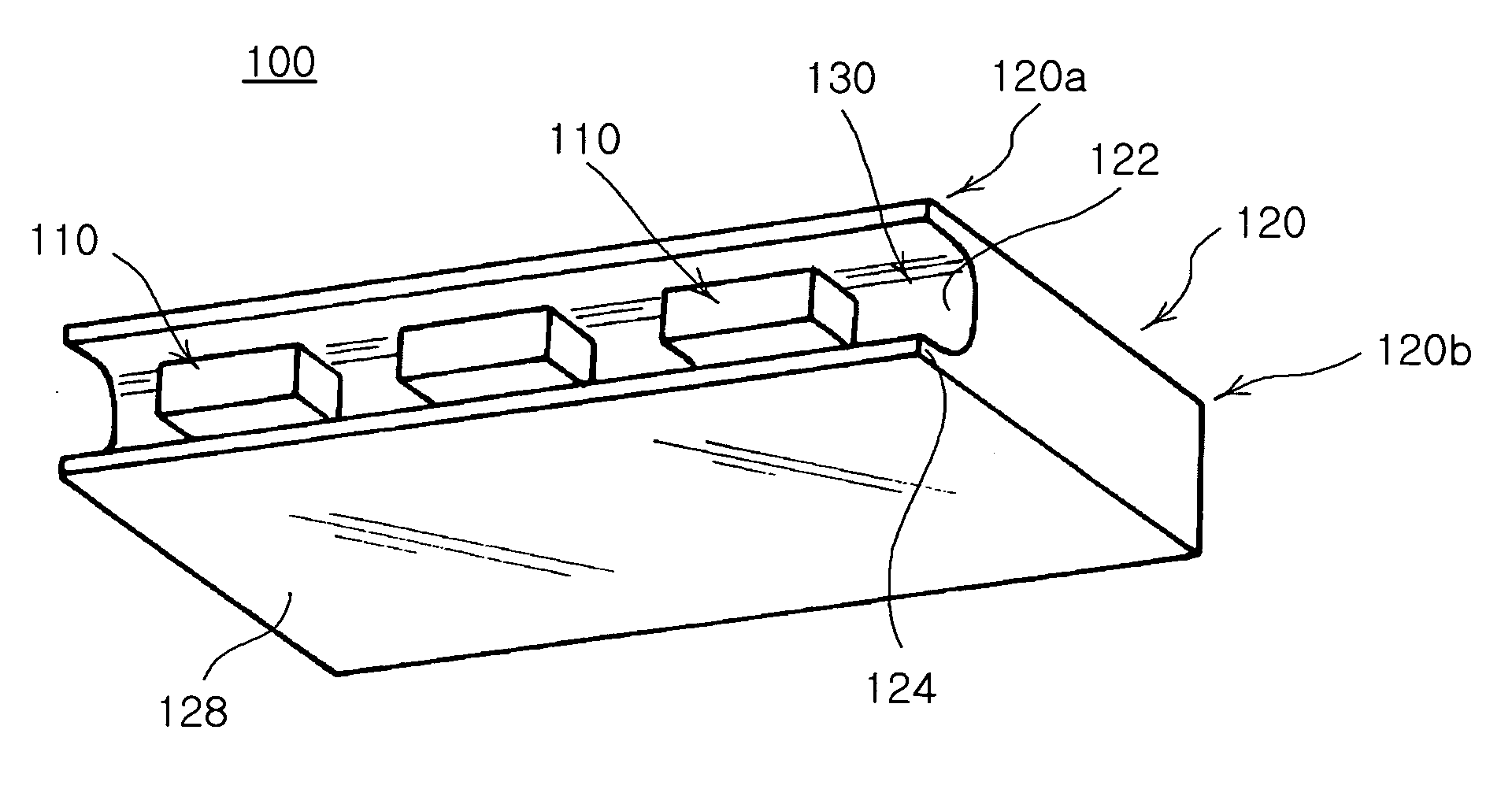
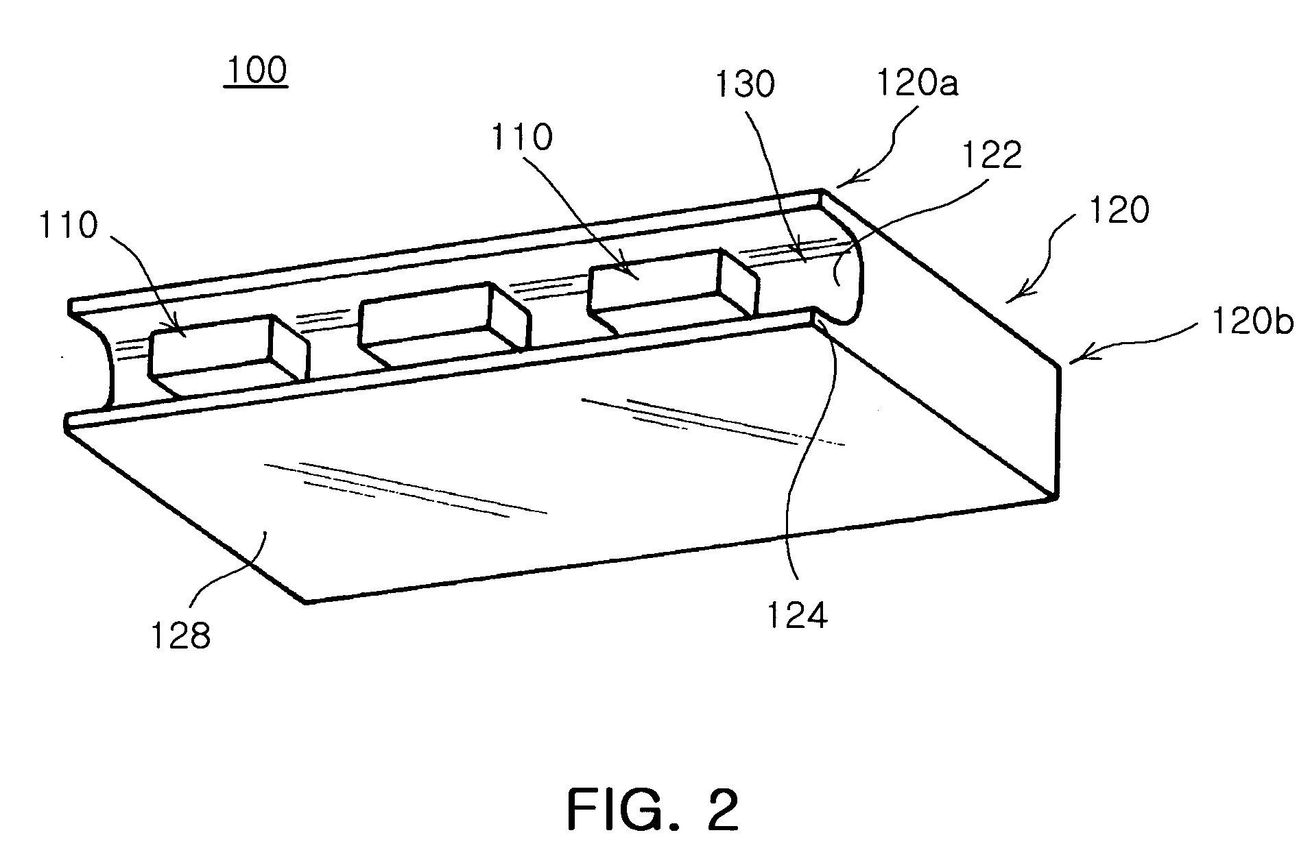
[0033]FIG. 2 is a perspective view illustrating an LED backlight device of the invention. FIG. 3 is a-front elevation view of FIG. 2 and FIG. 4 is a cross-sectional view cut along the line 4-4 of FIG. 3.

[0034] Referring to FIGS. 2 to 4, the LED backlight device 100 of the invention includes a light guide plate 120 and three LED packages 110. The light guide plate 120 has a recess 130 formed at one side thereof along a width direction except for edges. The three LED packages 110 accommodated in the recess function as a light source. Here, the three LED packages 110 are illustrated as exemplary and the number of the LED packages 110 may be varied if necessary.

[0035] Also, although not illustrated but as known in the art, the LED backlight device 100 of the invention further includes a housing, and a light scattering pattern and a reflecting plate dispose...


PUM


Abstract

An LED backlight device is provided. A light guide plate has opposing edges of a width direction at a side thereof extended into a pair of opposing walls and a recess formed therebetween. A light emitting diode (LED) light source is accommodated in the recess to project light into the light guide plate. In this fashion, the light guide plate has the recess formed at one side of the light guide plate to seat the LED package therein. This minimizes loss of light incident from the LED package into the light guide plate and allows the LED package to be aligned securely with the light guide plate.

Description

CLAIM OF PRIORITY [0001] This application claims the benefit of Korean Patent Application No. 2005-117160 filed on Dec. 2, 2005 in the Korean Intellectual Property Office, the disclosure of which is incorporated herein by reference. BACKGROUND OF THE INVENTION [0002] 1. Field of the Invention [0003] The present invention relates to a backlight device, more particularly a light emitting diode (LED) backlight device in which a recess is formed at one side of a light guide plate to seat an LED package therein, thereby minimizing loss of light incident from the LED package into the light guide plate and allows the LED package to be aligned securely with the light guide plate. [0004] 2. Description of the Related Art [0005] Liquid crystal displays (LCDs) require external light due to absence of its own light source and typically adopt a backlight device for lighting. The backlight device illuminates an LCD from behind and uses a Cold Cathode Fluorescent Lamp (CCFL) or LEDs as a light sou...

Claims


Application Information

Patent Timeline
IPC IPC(8): F21V7/04
CPCG02B6/0016G02B6/0021G02B6/0068G02F1/1335
Inventor AN, IN GEOLPARK, JONG JIN
Owner SAMSUNG ELECTRO MECHANICS CO LTD
Why Eureka
Try Eureka