Surface emitting device

Inactive Publication Date: 2007-06-07
ALPS ALPINE CO LTD
View PDF2 Cites 10 Cited by
  • Summary
  • Abstract
  • Description
  • Claims
  • Application Information

AI Technical Summary

Benefits of technology

[0024] Since one light guide plate individually corresponds to one light source and one prism, it is possible to make simple a manufacturing process, and clearly disting

Problems solved by technology

When the display device is mounted on an apparatus, for example, a cellular phone, it is difficult to achieve a reduction in size.
When different kinds of display are displayed at one time

Method used


Image

  • Surface emitting device
  • Surface emitting device
  • Surface emitting device

Examples


first embodiment

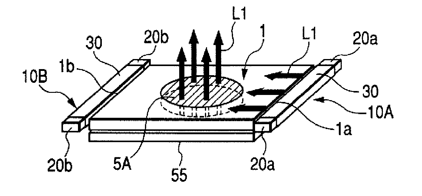
[0078] In this construction, in the same manner as the first embodiment, as one of the two light sources 10A and 10B is selectively turned on, the light from the prism 5A and 5B corresponding to the turned-on light source 10A and 10B is output toward the display surface. As the reflective sheet 55 reflects the light from the first or second prism 5A and 5B, the prism 5A and 5B outputs the light toward a common display surface, and the output light-irradiated regions on the display surface partially overlap each other or concentrically overlap each other. As shown in FIG. 10, when the first light source 10A is turned on, the light receiving surface 8 of the steep slope surface 5Ab of the first prism 5A formed on the first main surface 1c changes the optical path of the light L1 output from the first light source 10A so that the light proceeds toward the second main surface 1d and penetrates the gentle slope surface 5Bb of the second prism 5B, and then the reflective sheet 55 reflects...

second embodiment

[0083]FIGS. 12 and 13 are views showing the For example, as shown in FIG. 12, the first prism 5A is formed in a concavo-convex shape to have a light-emission pattern of a numeric keypad as shown in FIG. 12A, while the second prism 5B is formed in a concave-convex shape to have a light-emission pattern of a cross keypad as shown in FIG. 12B. For example, as modes are switched in an instrument having the surface emitting device 50A mounted therein by selectively turning on the first and second light sources 10A and 10B, it is possible to switchably display a numeric keypad (FIG. 12A) and a cross keypad (FIG. 12B) at one of the first and second main surfaces 1c and 1d (for example, the common display surface disposed so as to face the first main surface 1c). In another example, a screen display of the numeric keypad can be used as a phone number input unit during telephone calling in a mobile phone or the like, and a screen display of the cross keypad can be used as a rewind button of...


PUM


Abstract

A surface emitting device is provided. The surface emitting device includes a plurality of light sources; at least one light guide member; and a plurality of prisms that are disposed on the main surfaces of the light guide member corresponding to the light sources that are formed by convex-concave portions and change the optical path of light from the light sources toward the display surface. The surface emitting device is operable to display only light from the prism corresponding to a turned-on light source.

Description

[0001] This patent document claims the benefit of Japanese Patent Application 2005-303267 filed Oct. 18, 2005, which is hereby incorporated by reference. BACKGROUND [0002] 1. Field [0003] The present embodiments relate to a surface emitting device. [0004] 2. Related Art [0005] A light guide member has been used for various purposes, for example, in a backlight device serving as an illumination unit of a liquid crystal display device. The backlight device has a light source, a light guide plate that emits light from the light source to a liquid crystal display panel, and a prism that efficiently supplies light from the light guide plate to the liquid crystal display panel. The light guide plate is in a flat plate shape, and has a pair of main surfaces facing each other and a pair of end surfaces facing each other. In this case, the liquid crystal display panel is disposed on one of the main surfaces, and the light source is disposed in the vicinity of one of the end surfaces. A refle...

Claims


Application Information

Patent Timeline
IPC IPC(8): F21V7/04
CPCG02B6/0038G02B6/006G02B6/0068G02B6/0076
Inventor SUGIURA, TAKURONAGAKUBO, HIDEAKI
Owner ALPS ALPINE CO LTD
Why Eureka
Try Eureka