System and method for generating treatment patterns

Inactive Publication Date: 2007-06-07
TOPCON MEDICAL LASER SYST INC
View PDF22 Cites 142 Cited by
  • Summary
  • Abstract
  • Description
  • Claims
  • Application Information

AI Technical Summary

Problems solved by technology

While this type of visible laser light treatment halts the progress of the underlying disease, it can be problematic.
For example, because the treatment entails exposing the eye to visible laser light for a long period of time (typically on the order of 100 ms), damage can be caused to the patient's sensory retina from the heat that is generated.
Although light is absorbed in the RPE, this type of treatment irreversibly damages the overlying sensory retina and negatively affects the patie

Method used


Image

  • System and method for generating treatment patterns
  • System and method for generating treatment patterns
  • System and method for generating treatment patterns

Examples


Embodiment Construction

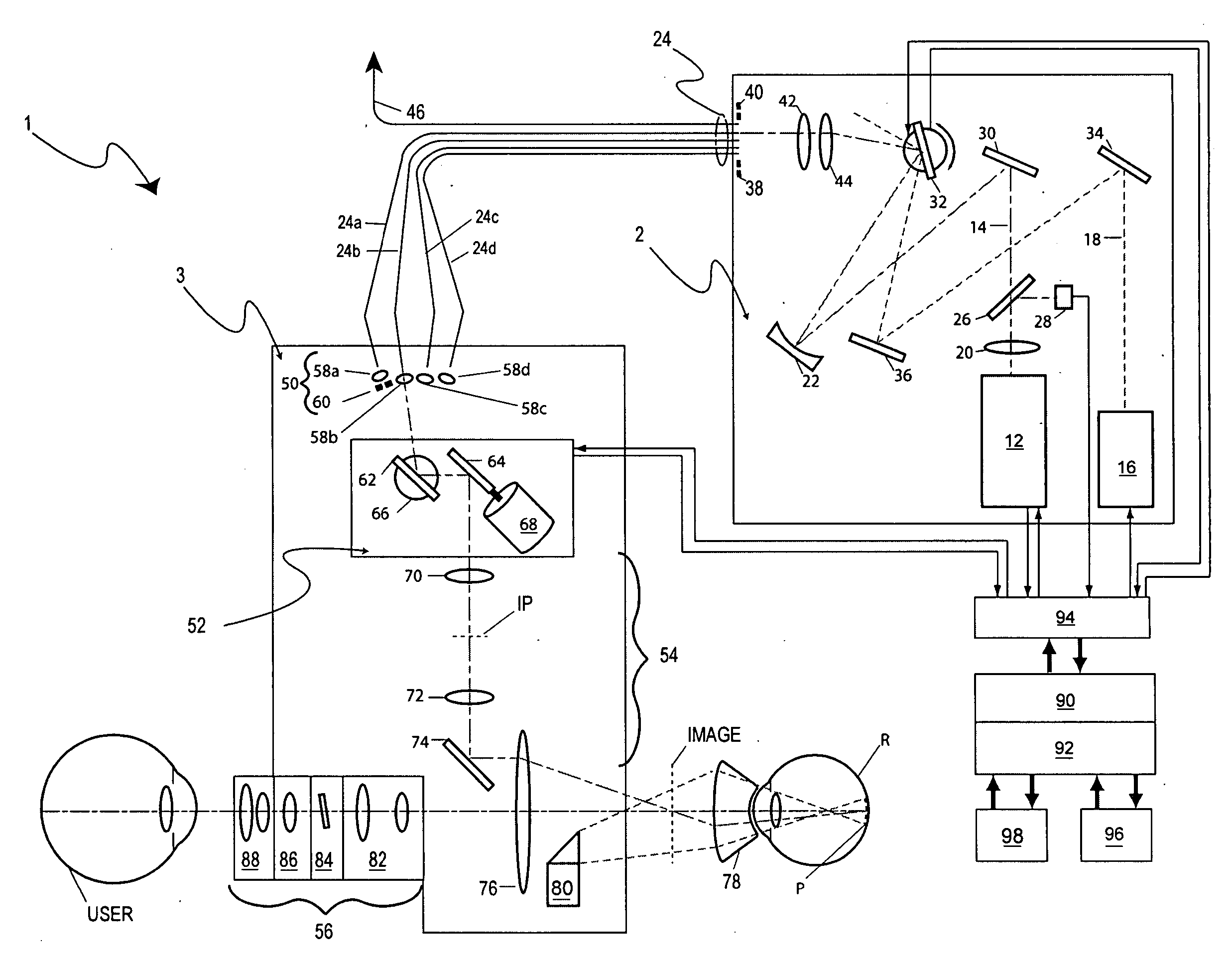
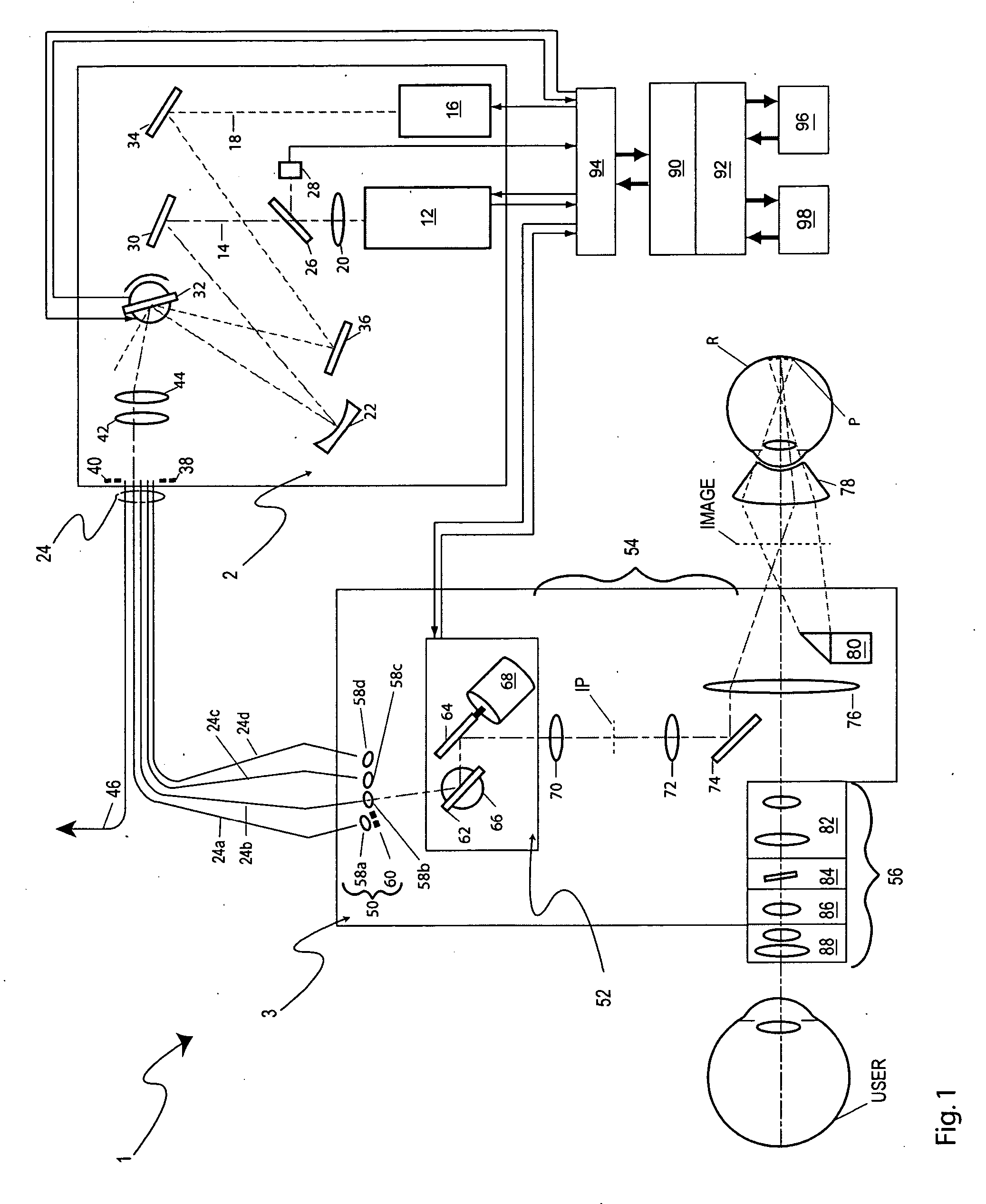
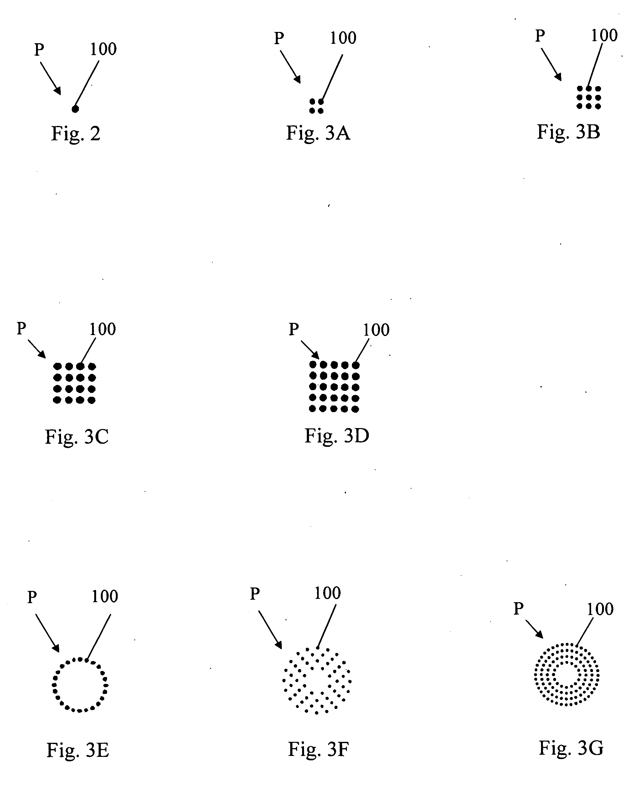
[0028] The present invention is a system and method for generating patterns P of aiming and treatment light on target eye tissue (e.g. the retina) of a patient's eye. FIG. 1 depicts an ophthalmic slit lamp based scanning photocoagulator 1, which is a non-limiting example of a photocoagulation system for creating and projecting aiming and / or treatment patterns of spots onto a patient's retina R. System 1 includes a light source assembly 2 and a slit lamp assembly 3.

[0029] The light source assembly 2 includes a treatment light source 12 for generating an optical beam of treatment light 14, and an aiming light source 16 for generating an optical beam of aiming light 18. Treatment beam 14 from treatment light source 12 is first conditioned by lens 20, which is used in conjunction with a curved mirror 22 to prepare treatment beam 14 for input into an optical fiber bundle 24. After encountering lens 20, treatment beam 14 is sampled by partially reflecting mirror 26. The light reflected f...


PUM


Abstract

System and method for generating patterns P of aiming and treatment light on target eye tissue (e.g. the retina) of a patient's eye. The system includes light sources for treatment and aiming light, a scanner for generating patterns of spots of the generated light, a controller, and a graphic user interface that allows the user to select one of several possible spot patterns, adjust the spot density and/or spot size, and apply patterns with fixed or varied density. The patterns can be formed of interlaced sub-patterns and/or scanned without adjacent spots being consecutively formed to reduce localized heating. Partially or fully enclosed exclusion zones within the patterns protect sensitive target tissue from exposure to the light.

Description

[0001] This application claims the benefit of U.S. Provisional Application No. 60 / 718,762, filed Sep. 19, 2005, and of U.S. Provisional Application No. 60 / 758,169, filed Jan. 10, 2006, both of which are hereby incorporated by reference.FIELD OF THE INVENTION [0002] The present invention relates to retinal photocoagulation, and more particularly to a system and method for patterned optical ophthalmic treatment. BACKGROUND OF THE INVENTION [0003] Presently, conditions such as diabetic retinopathy and age-related macular degeneration are subject to photocoagulative treatment with visible laser light. While this type of visible laser light treatment halts the progress of the underlying disease, it can be problematic. For example, because the treatment entails exposing the eye to visible laser light for a long period of time (typically on the order of 100 ms), damage can be caused to the patient's sensory retina from the heat that is generated. During the treatment, heat is generated pre...

Claims


Application Information

Patent Timeline
IPC IPC(8): A61N5/06A61B18/18
CPCA61B18/22A61B2018/2025A61B2018/2095A61B2018/2266A61B2018/2272A61F9/008A61F9/00821A61F2009/00863A61F2009/00897A61B2018/20359A61B2018/2035A61F9/00823A61F2009/00878
Inventor MORDAUNT, DAVID HAYDNMARCELLINO, GEORGEWILTBERGER, MICHAEL W.HENDRICKSON, JUSTINBELL, KATRINAANDERSEN, DAN E.
Owner TOPCON MEDICAL LASER SYST INC
Why Eureka
Try Eureka