Humidifier with back-flow prevention valve

Active Publication Date: 2007-06-14
PHILIPS RS NORTH AMERICA LLC
View PDF16 Cites 78 Cited by
  • Summary
  • Abstract
  • Description
  • Claims
  • Application Information

AI Technical Summary

Benefits of technology

[0010] Accordingly, it is an object of the present invention to provide a humidifier for use in a pressure support system that overcomes the shortcomings of conventional humidification devices. This object is achieved according to one embodiment of the present invention by providing a humidifier that includes a body having an inlet adapted to be operatively coupled to an outlet of a pressure support device such that a flow of gas generated by such a pressure support device is communicated to the inlet. The humidifier also includes a fluid holding chamber and an outlet. The inlet is positioned upstream and in fluid communication with the fluid holding chamber, and the outlet is positioned downstream of and in fluid communication with the fluid holding chamber. A valve is positioned in the inlet and upstream of the fluid chamber. The valve is movable between an open position in which the inlet is substantially unblocked and a closed position in which the inlet is substantially blocked.
[0011] It is a further object of the present invention to provide a pressure support system that overcomes the shortcomings of conventional pressure support systems. This object is achieved by providing a pressure support system that includes a pressure support device, which is adapted to generate a flow of gas, and a humidifier. The humidifier has a body having an inlet, a fluid holding chamber, and an outlet. The inlet is positioned upstream and in fluid communication with the fluid holding chamber, and the outlet is po

Problems solved by technology

Water entering pressure support device 10 could damage the device.
However, this configuration exacerbates the problem of fluid flowing from the humidification chamber back into the pressure support device, because of the direct and close connection between the inlet port of the humidification chamber and the outlet port of the pressure support device.
While the snorkel type of configuration taught by this patent may help minimize water from entering the outlet of the pressure support device due to backsplash or tilting of the system, it does not prevent water

Method used


Image

  • Humidifier with back-flow prevention valve
  • Humidifier with back-flow prevention valve
  • Humidifier with back-flow prevention valve

Examples


second embodiment

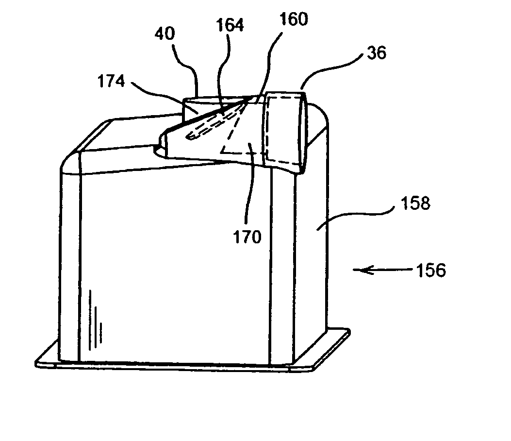
[0056]FIGS. 6-8 show humidifier 156 that includes a body 158 and a valve arrangement 160. Valve arrangement 160 includes a cylindrical member 162 having a flexible movable flap 164 attached thereto. In an exemplary embodiment, cylindrical member 162 is formed from a flexible material, such as silicone, rubber, or a combination thereof. Flap 164 is attached at one end 165 to cylindrical member 162 via a central portion 166. In an exemplary embodiment, cylindrical member 162, flap 164, and central portion 166 are formed form a unitary molded piece of material.

[0057] In an optional exemplary embodiment, a rigid overmolded ring or cylinder (not shown) is placed about a portion of the valve arrangement 160 to provide structure support for the valve. Valve 160 is adapted (sized and configured) to be positioned within inlet 36 of body 158. In an further optional embodiment, an exhaust vent 172 is positioned downstream of flap 164. Exhaust vent 172 includes a plurality of opening 174 to com...

third embodiment

[0061]FIGS. 9-12 illustrate a humidifier 256 that includes a body 258 and a valve arrangement 260 made in accordance with the principles of the present invention. This valve arrangement is similar to that as previously described valve arrangement 60. Valve arrangement 260 fits within inlet port 36. Specifically, valve arrangement 260 includes a cylindrically shaped overmolded arrangement 262 that receives a cylindrical ring 264. A valve element 266 is pivotably secured to the cylindrical ring 264 and / or overmolded arrangement 262. Valve element 266 includes a closure element or flap 268 and a counterweight blocking member or secondary flap 270 coupled thereto. Overmolded arrangement 262 includes an offset passageway that functions as an exhaust vent 272 to communicate a passage defined in cylindrical ring 264 and / or overmolded arrangement 262 with ambient atmosphere. An optional exhaust vent cover, such as a plurality of openings, can be positioned over exhaust vent 272. In an exemp...

fifth embodiment

[0068]FIGS. 16 and 17 illustrated a humidifier 330 having a body 332 and a valve arrangement, generally indicated at 334, according to the principles of the present invention. This embodiment is generally similar to the previous embodiment in that it uses a float valve, i.e., a ball 306, to selectively block and unblock a valve seat 316. The level of fluid 318 in a fluid holding chamber 336 of body 332 causes ball 306 to rise and fall within a support structure 338. Support structure 338, like support structure 307, guides the ball into the valve seat as the fluid rises or shifts in the fluid holding chamber. Preferably, support structure 338 allows gas and liquid to flow freely to ball 306.

[0069] During normal operation, as shown in FIG. 16, the level of fluid 318 is such that the ball is spaced apart from valve seat 316 and an substantially unobstructed gas flow path is provided at the inlet of the humidifier to the fluid holding chamber. Thus, gas flow relatively freely into the ...


PUM

PropertyMeasurementUnit
Pressureaaaaaaaaaa
Flow rateaaaaaaaaaa
Magnetic fieldaaaaaaaaaa

Abstract

A humidifier for use with a pressure support system. The humidifier includes a body having an inlet, a fluid holding chamber, and an outlet. The inlet is positioned upstream and in fluid communication with the fluid holding chamber. The outlet is positioned downstream of and in fluid communication with the fluid holding chamber. A back-flow preventing valve is positioned upstream of the fluid chamber. The back-flow preventing valve is movable between an open position, in which the inlet is unblocked, and a closed position in which the inlet is blocked. In the closed position, the back-flow preventing valve prevents fluid, fluid vapor, or both from entering the pressure support via the inlet to the humidifier.

Description

CROSS-REFERENCE TO RELATED APPLICATIONS [0001] This application claims priority under 35 U.S.C. § 119(e) from provisional U.S. patent application No. 60 / 720,763, filed Sep. 27, 2005, the contents of which are incorporated herein by reference.BACKGROUND OF THE INVENTION [0002] 1. Field of the Invention [0003] The present invention relates to a humidifier and, more particularly, to a humidifier used in a pressure support system that includes a valve to prevent a back-flow of fluid from the humidifier into a pressure support device. [0004] 2. Description of the Prior Art [0005] There are numerous situations where it is necessary or desirable to deliver a flow of breathing gas to the airway of a patient. For example, it is known to ventilate a patient using a technique known as non-invasive ventilation. It is also known to deliver continuous positive airway pressure (CPAP) or variable airway pressure, which varies with the patient's respiratory cycle or a monitored condition of the pati...

Claims


Application Information

Patent Timeline
IPC IPC(8): B01D47/02F24F3/14
CPCA61M16/16A61M16/162A61M16/208A61M16/109A61M16/202
Inventor PUJOL, J. RAYMONDTRUITT, PATRICK W.MARTIN, DANIELDUFF, WINSLOW K.KIMMEL, STEVEN A.KEPLER, JEFFERY
Owner PHILIPS RS NORTH AMERICA LLC
Why Eureka
Try Eureka