Self-contained adjustable air foil and method

a self-contained, adjustable technology, applied in the direction of roofs, heating types, lighting and heating apparatus, etc., can solve the problems of reducing the air pressure of the air foil system, unable to meet the needs of the device is not well suited to other air foil applications, so as to achieve the effect of reducing the air pressur

Inactive Publication Date: 2007-06-14
WEAVER DARRICK CHARLES
View PDF18 Cites 13 Cited by
  • Summary
  • Abstract
  • Description
  • Claims
  • Application Information

AI Technical Summary

Benefits of technology

[0009] The open position provides access from outside of the enclosure to a volume within the enclosure. Consequently, if the one edge of the air foil panel is oriented closest to a rear end of the vehicle, an underside of the air foil will act as a scoop to redirect air into the enclosure. On the other hand, if the one edge of the air foil panel is oriented closest to a front end of the vehicle, the air foil panel in the open position will act as a spoiler and will reduce air pressure at the underside of the air foil panel, resulting in a Venturi effect imparted upon the volume inside the enclosure.
[0010] An actuator interconnects the underside of the air foil panel with the interior side of the base plate and allows for selective moving of the air foil panel between the open and closed positions. The actuator is pivotably connected to the base plate and the air foil panel, such that as the actuator changes length the rotational position of the air foil panel with respect to the base plate is also changed.

Problems solved by technology

Moreover, there are very few options for adding such an active air foil system on existing vehicles.
However, such a device is not well suited for other air foil applications, such as direction air into an engine cooling or air intake system, for example.
Further, when such a device is in its un-deployed position for minimizing the amount of aerodynamic drag that it creates, a significant amount of additional drag is still created due to the open, uncovered design of such a device.
However, this prior art device is not suitable for use on any vehicle other than a trucking cab, such as on automobiles or the like, due to its specific shape requirements for diverting airflow up and over a trailer.
Further, use as an auxiliary air intake device for other applications is not contemplated.
Installation of such a device on an existing vehicle would result in a minimum of damage to the outer surface of the vehicle.

Method used


Image

  • Self-contained adjustable air foil and method
  • Self-contained adjustable air foil and method
  • Self-contained adjustable air foil and method

Examples


Embodiment Construction

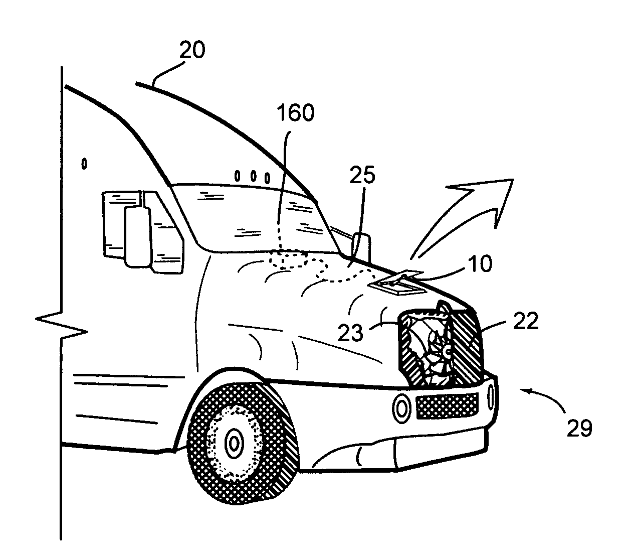
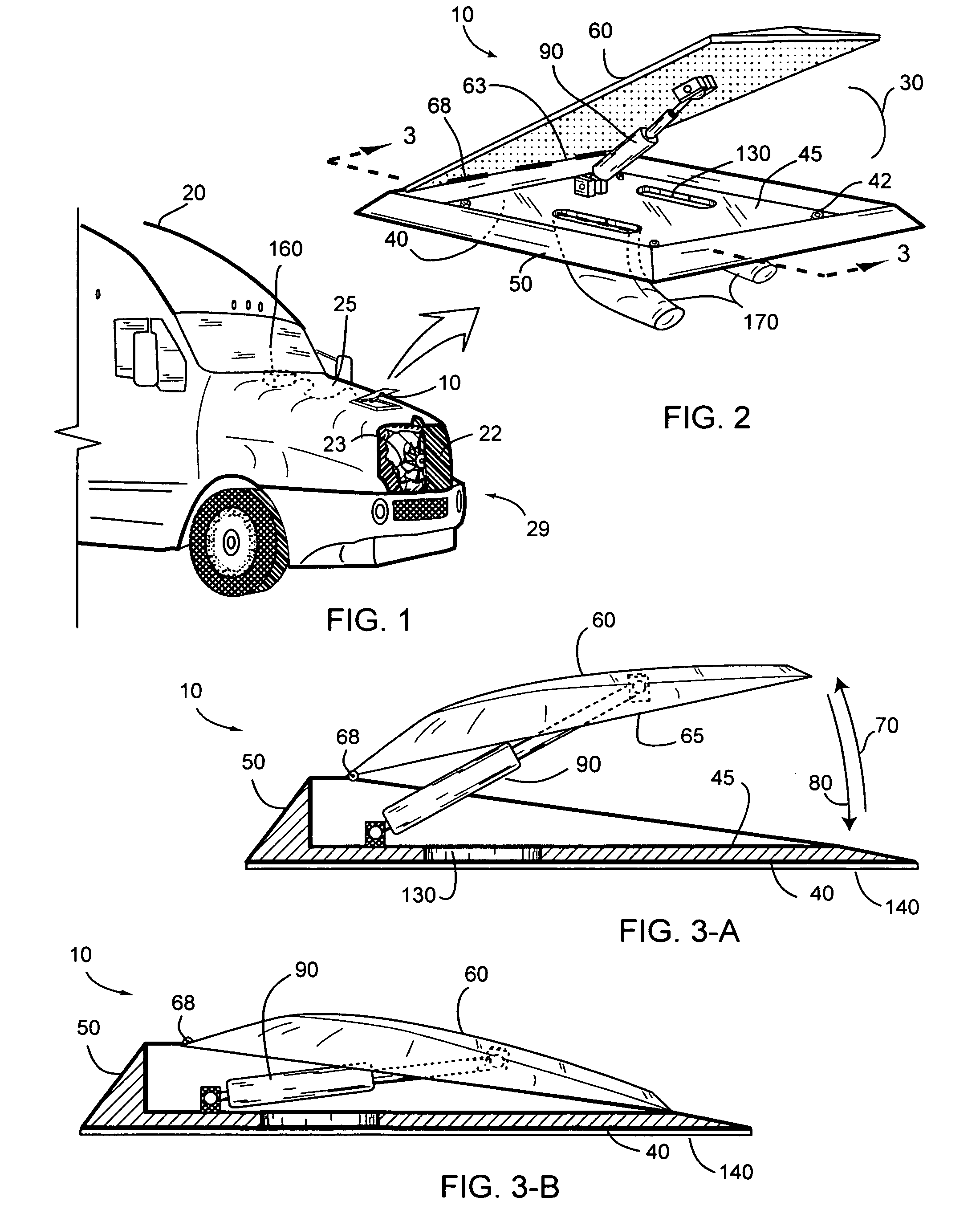
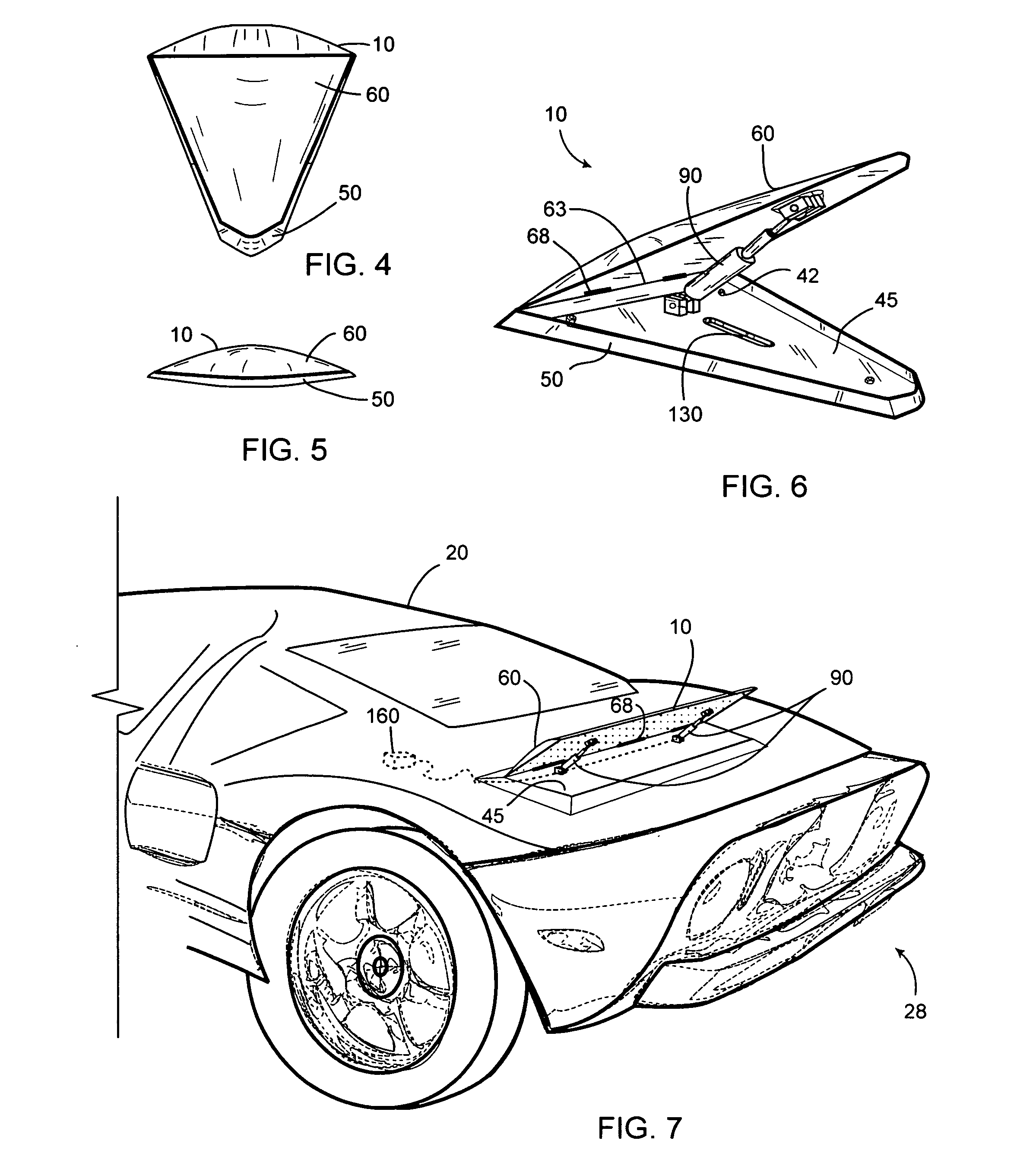
[0025]FIG. 1 illustrates an auxiliary air foil device 10 for mounting on a vehicle 20. The vehicle 20, such as a truck illustrated in FIG. 1, or a high performance automobile shown in FIG. 7, has an outer surface 25 that is suitably flat for mounting of the air foil device 10, the outer surface 25 being immediately adjacent to a stream of air flowing around the vehicle 20 when the vehicle 20 is in motion.

[0026] The air foil device 10 includes an enclosure 30 comprising a base plate 40, a plurality of side walls 50, and an air foil panel 60. The base plate 40 includes an interior side 45 that is attached proximate to a lower edge 55 of each of the side walls 50. One edge 63 of the air foil panel 60 is pivotably connected at a plurality of hinges 68 to an upper edge 57 of at least one of the side walls 50. As such, the air foil panel 60 is pivotable between an open position 70 and a closed position 80 (FIGS. 3-A and 3-B). In the closed position 80, the outside air flow will be substa...


PUM


Abstract

An auxiliary air foil device for mounting on a vehicle is disclosed. The air foil device includes an enclosure comprising a base plate, a plurality of side walls, and an air foil panel. The air foil panel is pivotable between an open position and a closed position. In the closed position, the outside air flow will be substantially isolated from the volume within the enclosure. The open position provides access from outside of the enclosure to a volume within the enclosure. An actuator interconnects the underside of the air foil panel with the interior side of the base plate and allows for selective moving of the air foil panel between the open and closed positions. The actuator is pivotably connected to the base plate and the air foil panel, such that as the actuator changes length the rotational position of the air foil panel with respect to the base plate is also changed. In use, depending upon the application desired, the auxiliary air foil device of the present invention may be used as an air brake for the vehicle, as a means for increasing air flow into an engines air intake or cooling systems, as an adjustable spoiler, as a vacuum source for exhaust or other systems, or the like. The air foil device may be oriented with the pivoted edge of the air foil panel oriented towards either the front or rear end of the vehicle, and apertures in the base plate may be connected through the vehicle surface to optional air ducting means for delivering additional airflow or requiring it.

Description

RELATED APPLICATIONS [0001] The present invention is a continuation-in-part of US Patent Application 2004 / 0212219A1, filed on Apr. 22, 2003, which is hereby incorporated in its entirety by reference.STATEMENT REGARDING FEDERALLY SPONSORED RESEARCH AND DEVELOPMENT [0002] Not Applicable. FIELD OF THE INVENTION [0003] This invention relates to air foil devices for vehicles, and more particularly to a self- contained adjustable air foil for attaching to an existing vehicle, or the like. DISCUSSION OF RELATED ART [0004] Consumer automobiles and other vehicles rarely have active air foil systems installed that allow the vehicle to take advantage of the wind stream passing around the vehicle for use as added braking or air flow into the engine air intake or cooling systems. While some vehicles have static structures to direct air flow into the engine, such as static air scoops or the like, or for aerodynamically pulling the vehicle closer to the ground for better traction, few vehicles hav...

Claims


Application Information

Patent Timeline
Patent Type & Authority Applications(United States)
IPC IPC(8): B60J9/04
CPCB60H1/26B62D35/005B62D35/007Y02T10/82
Inventor WEAVER, DARRICK CHARLES
Owner WEAVER DARRICK CHARLES
Why Eureka
Try Eureka