Car seat

a seat and seat technology, applied in the field of car seats, can solve the problems the seat belts did not work effectively, and the effect of deteriorating the comfort of the seat, and achieve the effect of not being able to achieve the effect of preventing the passenger from moving forward, and being easy to catch

Inactive Publication Date: 2007-06-14
DAIHATSU MOTOR CO LTD
View PDF16 Cites 12 Cited by
  • Summary
  • Abstract
  • Description
  • Claims
  • Application Information

AI Technical Summary

Benefits of technology

[0011] The 
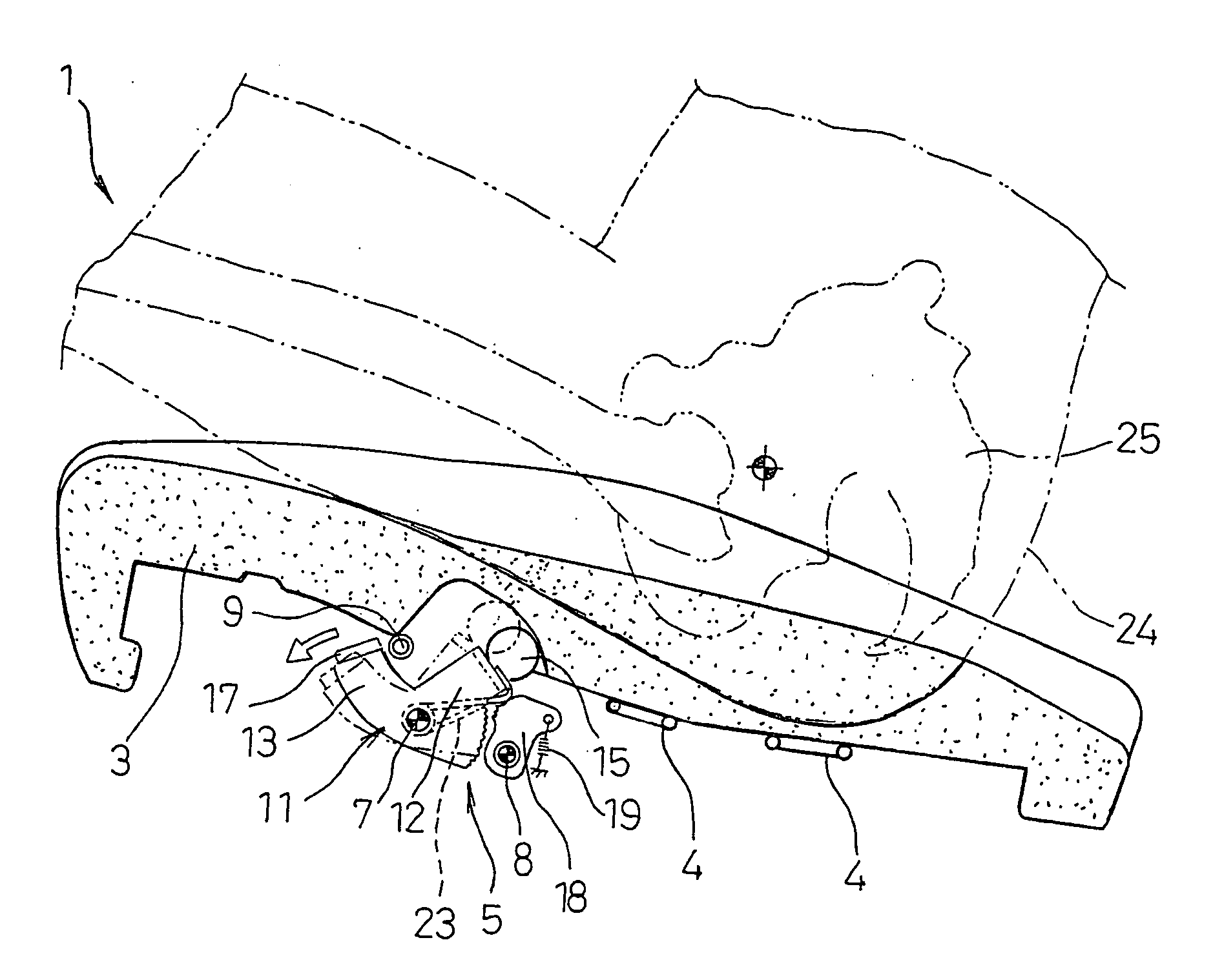
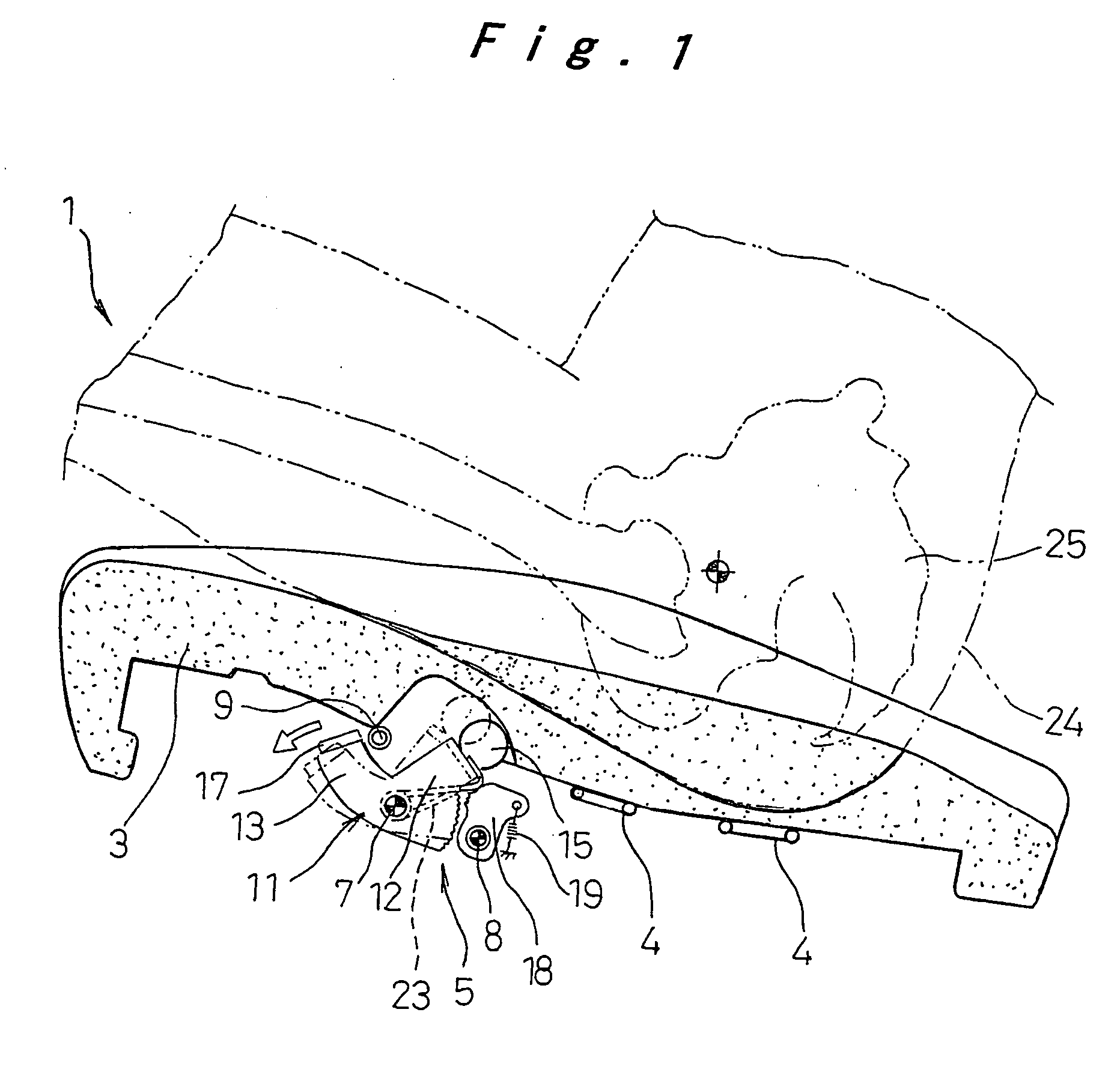
car seat of the present invention includes, in a front part inside the seat cushion, a catching part extending in a widthwise direction of the seat cushion and arranged such as to be movable up and down, and inertial force application means that is activated by an inertial force at the time of rapid deceleration to move the catching part upward. With this design, when a passenger sits on the seat cushion, the catching part moves down easily by the pressure from above, so that any feeling that there is something underneath is reduced and the seat comfort is not deteriorated, and in the event of rapid deceleration caused by a front collision, the inertial force application means is activated and the catching part is moved upward by inertia, so that any forward movement of the passenger's hips is stopped by this catching part, and thus it is reliably prevented that the passenger moves forward, and since there are no lift-up mechanism or drive means, the structure is simple, lightweight, and low-cost.
[0012] The catching part is supported by a reinforcing member inside the seat cushion such that it is swingable up and down around a pivot shaft on the rear side of the vehicle relative to the pivot shaft, and the inertial force application means includes an inertial mass part arranged forward of the catching part and its pivot shaft and above the pivot shaft, and a coupling part for connecting the inertial mass part and the catching part. Thereby, the catching part moves upward as well as forward so that it easily catches the passenger's hips moving forward during rapid deceleration, and also because the inertial mass application means is arranged forward of and above the pivot shaft, the entire mechanism is made compact in the up and down direction and readily accommodated inside the seat. Moreover, since the moment of inertia on the catching part and on the inertial mass part changes mutually complementarily during rapid deceleration, the catching part is moved upward by inertia stably throughout the swing.
[0013] The catching part may be coupled to a support spring member that supports the lower side of the seat cushion, using an elastic member having a smaller maximum tension force than the inertial force that acts during rapid deceleration. Thereby, when the passenger sits on the seat, the seat cushion displaces downward and the support spring member is flexed, pulling the catching part downward through the elastic member, whereby it is more reliably prevented that the passenger feels there is something underneath when s / he sits down because of the catching part, while the performance for stopping the passenger's motion during rapid deceleration is achieved.
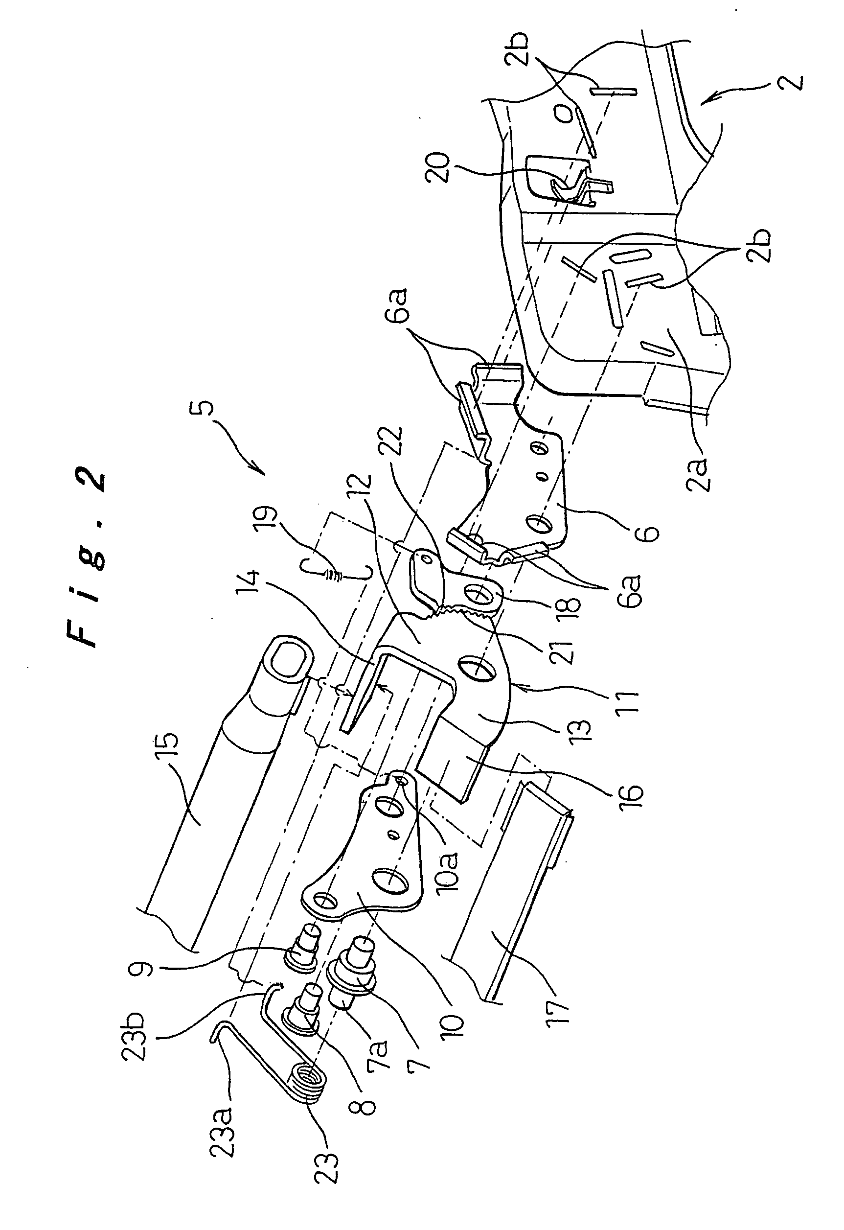
[0014] Locking means may be provided for stopping downward movement of the catching part that has been moved upward by the inertial force during rapid deceleration, so that the catching part remains in its upward position and does not move down and the effect of catching the passenger's hips is achieved in a stable manner, whereby it is reliably prevented that the passenger moves forward.
[0015] The catching part and the inertial mass part are coupled together and supported by a support member; the locking means may be composed of a locking member that is always kept in contact with this support member with biasing means, and an engagement portion formed to the support member to be engaged with the locking member when the catching part moves more than a predetermined distance. Thereby, as the locking member is always kept in contact with the support member, it responds immediately to any sudden movement of the catching part so that the passenger is reliably stopped from moving forward, and also, as the support member and the locking member are in contact with each other, the design is compact.
[0016] The support member may have two extensions from the pivot shaft toward the catching part side and the inertial mass part side, the latter being substantially J-shaped when viewed from one side of the vehicle. The locking member may be arranged on the front side of the vehicle relative to the support member, a curved portion at the front end of the letter J of the support member forming an engagement portion to be engaged with the locking member. Thereby, the support member need not be provided with an additional component to form the engagement portion, and the design is made simpler and compact, while the locking effect is reliably achieved.

Problems solved by technology

One problem, however, was that seat belts did not work effectively when the passengers' hips move forward as they sink into seat cushions.
With this approach, the cross member catches the passenger's hips, so that shock is absorbed by the deformation of the cross member and that the passenger's forward movement is restricted.
However, there is a problem that such a cross member in the front part of the seat cushion will make the seated passenger uncomfortable and deteriorate driving comfort, but on the other hand if the cross member is positioned lower enough so as not to affect seat comfort, then the effect of preventing the passenger from moving forward will not be achieved.
However, with the design shown in Japanese Patent Publication No. 5-238297, the seat cushion lift-up means and movable member, as well as means of linking these, are required, because of which the structure is large, complex, and expensive.
Another problem is that the movable member adversely affects the seat comfort.
With the design shown in Japanese Patent Publication No. 2000-1136, the mechanism for lifting up the cross member forcibly when necessary and its drive means are required, because of which the system is complex and expensive, and also heavy.
WO02 / 066285, the structure is simple and the seat comfort when the passenger sits down is not bad; however, there is a possibility that, when the passenger's hips move forward in a front collision, the catching member may slip down due to a downward force component of the load applied to the catching member, because of which there is a reliability problem in the effect of preventing forward movement of the passenger.

Method used


Image

  • Car seat
  • Car seat
  • Car seat

Examples


Embodiment Construction

[0027] Preferred embodiments of the car seat of the present invention will be hereinafter described with reference to FIG. 1 to FIG. 10D.

[0028] A first embodiment of the present invention is described first with reference to FIG. 1 to FIG. 4. In FIG. 1 and FIG. 2, numeral 1 denotes a car seat cushion, and 2 denotes a steel plate frame part of the seat cushion 1, both sides of which are attached to upper rails of left and right seat rails (not shown). A cushion pad 3 made of, for example, urethane foam is mounted on this frame part 2, and is covered by an outer package material (not shown). A plurality of S springs 4 are stretched at the bottom of the frame part 2 across the side plates, spaced from each other in the front to back direction in the middle and at the rear part in the front to back direction of the vehicle, serving as support spring members for supporting the lower side of the cushion pad 3. In the front part between the side plates of the frame part 2 beneath the cush...


PUM


Abstract

In a front part inside a seat cushion are arranged a catching member extending in a widthwise direction of the seat cushion and movable up and down, and inertial force transmission means for moving the catching member upward by the inertial force that acts on an inertial mass at the time of rapid deceleration. When a passenger sits on the seat cushion, the catching member moves down so as not to deteriorate the seat comfort, and at the time of rapid deceleration, the catching member moves up and stops the passenger's hips from moving forward. Thus it is reliably prevented that the passenger moves forward, without deteriorating the seat comfort, and the design is simple, lightweight, and low-cost.

Description

TECHNICAL FIELD [0001] The present invention relates to a car seat, and more particularly to a car seat that prevents the passenger from moving forward when the car is suddenly decelerated. BACKGROUND ART [0002] Conventionally, seat belts are provided as means of preventing passengers from moving forward by the force of inertia when the car is suddenly decelerated. One problem, however, was that seat belts did not work effectively when the passengers' hips move forward as they sink into seat cushions. [0003] To prevent passenger's hips from moving forward, it has been proposed to provide a cross member such as a pipe inside the seat cushion bridged across the width of the seat cushion in a position forward of the hips of the passenger in a normal seated position. With this approach, the cross member catches the passenger's hips, so that shock is absorbed by the deformation of the cross member and that the passenger's forward movement is restricted. [0004] However, there is a problem...

Claims


Application Information

Patent Timeline
Patent Type & Authority Applications(United States)
IPC IPC(8): B60N2/427
CPCB60N2/4221B60N2/42763B60N2/42781B60N2/42B60N2/427
Inventor TAOKA, YOSHIFUMIUSHIJIMA, TETSUROU
Owner DAIHATSU MOTOR CO LTD
Why Eureka
Try Eureka