Video mirror system suitable for use in a vehicle

a technology for video mirrors and vehicles, applied in television systems, vehicle cleaning, instruments, etc., can solve the problems of limiting its commercial use and success, deteriorating the driver's ability to efficiently and safely use the interior rearview mirror assembly, etc., to achieve the effect of maximizing the rearward field of view and readily viewing the images displayed by the video screen

Inactive Publication Date: 2007-06-14
DONNELLY CORP
View PDF99 Cites 158 Cited by
  • Summary
  • Abstract
  • Description
  • Claims
  • Application Information

AI Technical Summary

Benefits of technology

[0004] One objective of this invention is to provide a video screen at an interior mirror assembly in a way that maximizes rearward field of view by the reflector element and that enables the driver to readily view images displayed by the video screen. A further objective is

Problems solved by technology

Although the known assembly as described in FIG. 1 can operate in certain circumstances, there are disadvantages that limit its commercial use and success.
Thus, the rearward field of vie

Method used


Image

  • Video mirror system suitable for use in a vehicle
  • Video mirror system suitable for use in a vehicle
  • Video mirror system suitable for use in a vehicle

Examples


Embodiment Construction

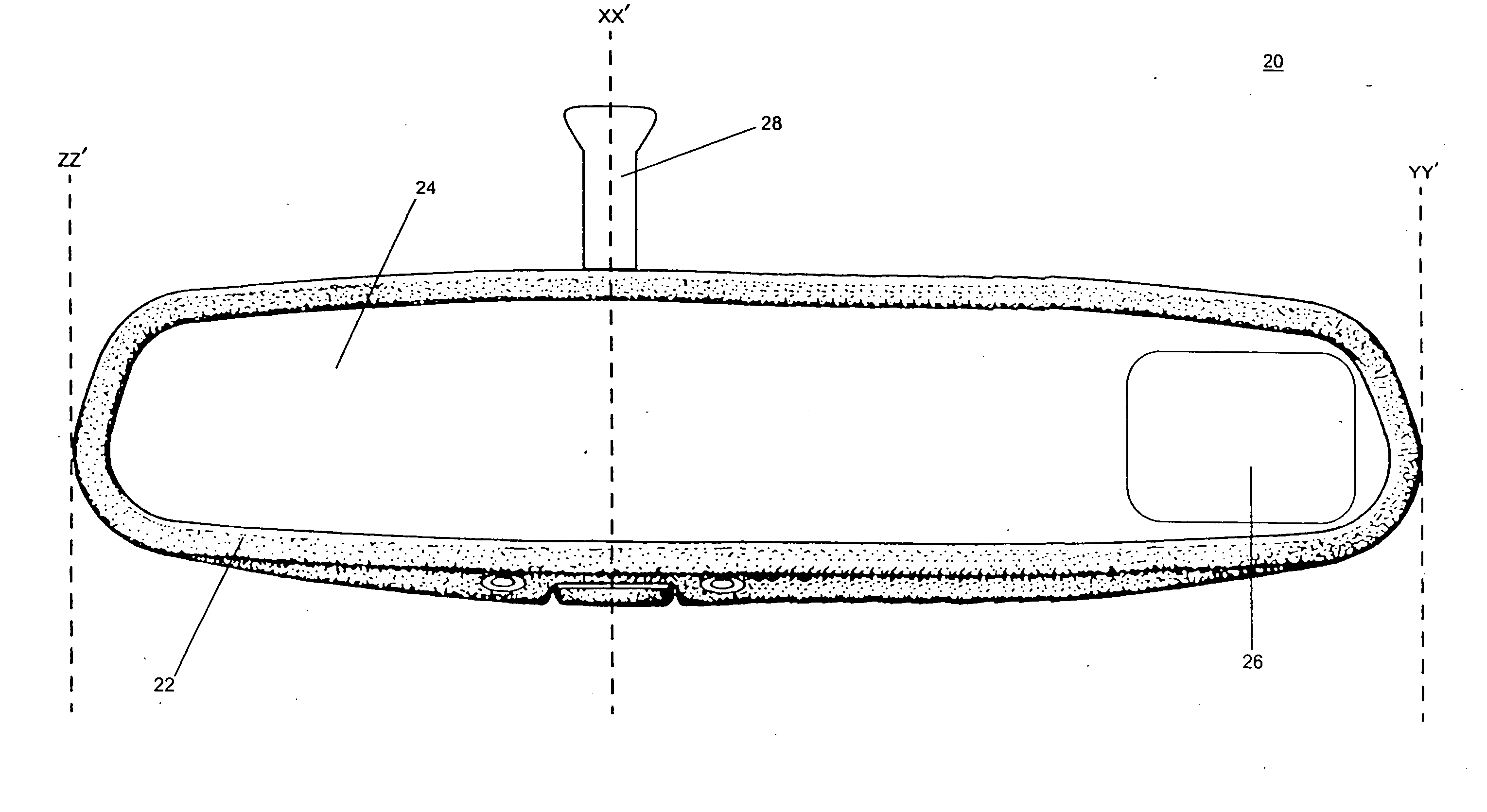
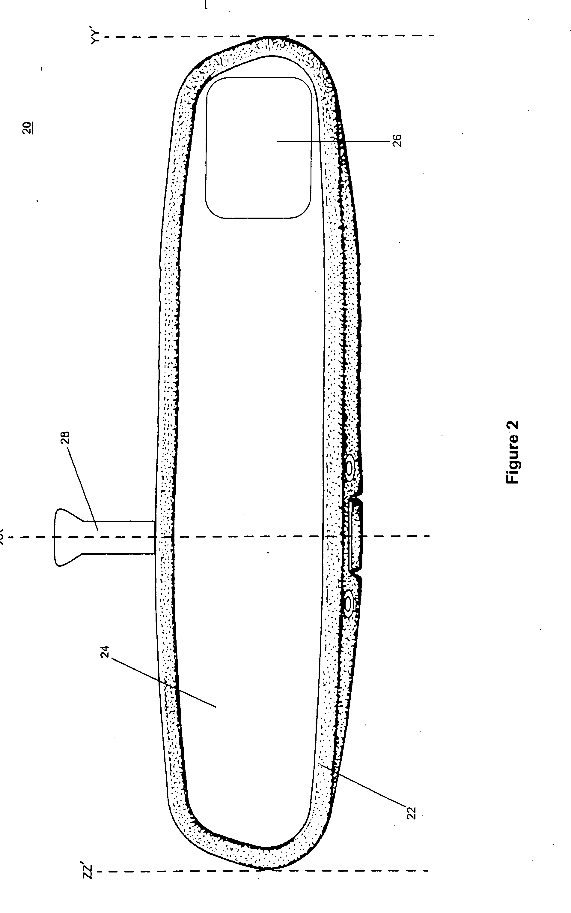
[0233] An improved interior rearview mirror assembly of the present invention is shown in FIG. 2. Interior rearview mirror assembly 20 is adapted for use in a left-hand drive vehicle. Thus, when interior rearview mirror assembly 20 is attached in or at an interior of a vehicle (such as to a windshield or to a header portion of the vehicle interior cabin, as known in the mirror arts), the driver of the vehicle is seated closer to portion ZZ′-XX′ (see FIG. 2) than to portion XX′-YY′. Video screen 26 is in portion XX′-YY′ of mirror casing 22 at a location as close as can be accommodated to the end of casing 22 farthest from the seating position of the driver in the vehicle. Casing 22 attaches to the vehicle via a mirror support arm 28 that projects from the rear (or alternately from the top) of casing 22 at a mounting portion located at a vertical cross-sectional line XX′. Thus, and importantly, the distance from ZZ′ to XX′ is less than the distance from XX′ to YY′ and the point of att...


PUM


Abstract

A vehicular video mirror system comprises an interior electrochromic mirror having a transflective mirror reflector and a video screen disposed behind the mirror reflector so that the presence of the video screen is substantially unobservable to a driver of the vehicle until the video screen is actuated to emit light that passes through the electrochromic reflective element to be viewed by the driver of the vehicle. Control circuitry receives a signal indicative of selection of a reverse gear of the vehicle by the driver and actuates the video screen in order to display video images captured by a video imaging device disposed to the rear of the vehicle and having a field of view rearward of and external to the vehicle.

Description

CROSS REFERENCE TO RELATED APPLICATIONS [0001] This application is a continuation of pending U.S. patent application Ser. No. 10 / 755,915, filed Jan. 13, 2004 entitled VIDEO MIRROR SYSTEMS INCORPORATING AN ACCESSORY MODULE (Attorney Docket DON01 P-1133), which is a continuation of U.S. application Ser. No. 09 / 793,002, filed Feb. 26, 2001, now U.S. Pat. No. 6,690,268 (DON01 P-869), which claims benefit of and incorporates by reference herein in their entireties U.S. provisional applications, Ser. No. 60 / 263,680, filed Jan. 23, 2001 (DON01 P-876); Ser. No. 60 / 243,986, filed Oct. 27, 2000 (DON01 P-857); Ser. No. 60 / 238,483, filed Oct. 6, 2000 (DON01 P-849); Ser. No. 60 / 237,077, filed Sep. 30, 2000 (DON01 P-846); Ser. No. 60 / 234,412, filed Sep. 21, 2000 (DON01 P-841); Ser. No. 60 / 218,336, filed Jul. 14, 2000 (DON01 P-831); and Ser. No. 60 / 186,520, filed Mar. 2, 2000 (DON01 P-802).BACKGROUND OF THE INVENTION [0002] Practically every passenger-carrying vehicle (such as sedans, convertibles...

Claims


Application Information

Patent Timeline
IPC IPC(8): B60Q1/00B60C23/00B60C23/04B60K35/00B60Q1/26B60Q1/50B60Q1/54B60Q3/02B60R1/04B60R1/12B60R11/00B60R11/02B60R11/04B60R21/01B60R21/015B60S1/08G02B6/00G02B27/00G02B27/01G06Q20/00
CPCB60C23/00B60R21/01566B60K35/00B60K37/06B60K2350/1024B60K2350/1028B60Q1/22B60Q1/2665B60Q1/503B60Q1/54B60Q3/023B60R1/00B60R1/04B60R1/06B60R1/12B60R1/1207B60R11/0235B60R11/0241B60R11/0247B60R11/04B60R2001/1215B60R2001/1223B60R2001/1253B60R2001/1284B60R2011/0026B60R2011/0033B60R2011/004B60R2011/0082B60R2011/0084B60R2011/0089B60R2011/0282B60R2011/0288B60R2011/0294B60R2300/103B60R2300/105B60R2300/106B60R2300/302B60R2300/406B60R2300/8026B60R2300/804B60R2300/8053B60R2300/806B60S1/0822B60S1/0844B60S1/0885G02B6/00G02B27/01G02B27/0101G02B2027/0118G02B2027/012H04N7/18H04N5/2253B60C23/0408B60K2370/143B60K2370/1438B60Q3/258B60Q1/50B60Q1/543B60Q1/5037B60R1/02
Inventor SCHOFIELD, KENNETHO'BRIEN, FRANKBINGLE, ROBERT L.LYNAM, NIALL R.
Owner DONNELLY CORP
Why Eureka
Try Eureka