
Masking to prevent overexposure and light spillage in microarray scanning

a microarray and scanning technology, applied in the field of scanning systems for microarrays, can solve the problems of overexposure or photobleaching of site contents, certain degree of light spillage to adjacent wells, and certain sites to receive greater exposure than others, so as to prevent the spread of light onto adjacent rows, shorten the length, and prevent non-uniform exposure of sites

Inactive Publication Date: 2007-06-14
BIO RAD LAB INC
View PDF16 Cites 5 Cited by
  • Summary
  • Abstract
  • Description
  • Claims
  • Application Information

AI Technical Summary

Benefits of technology

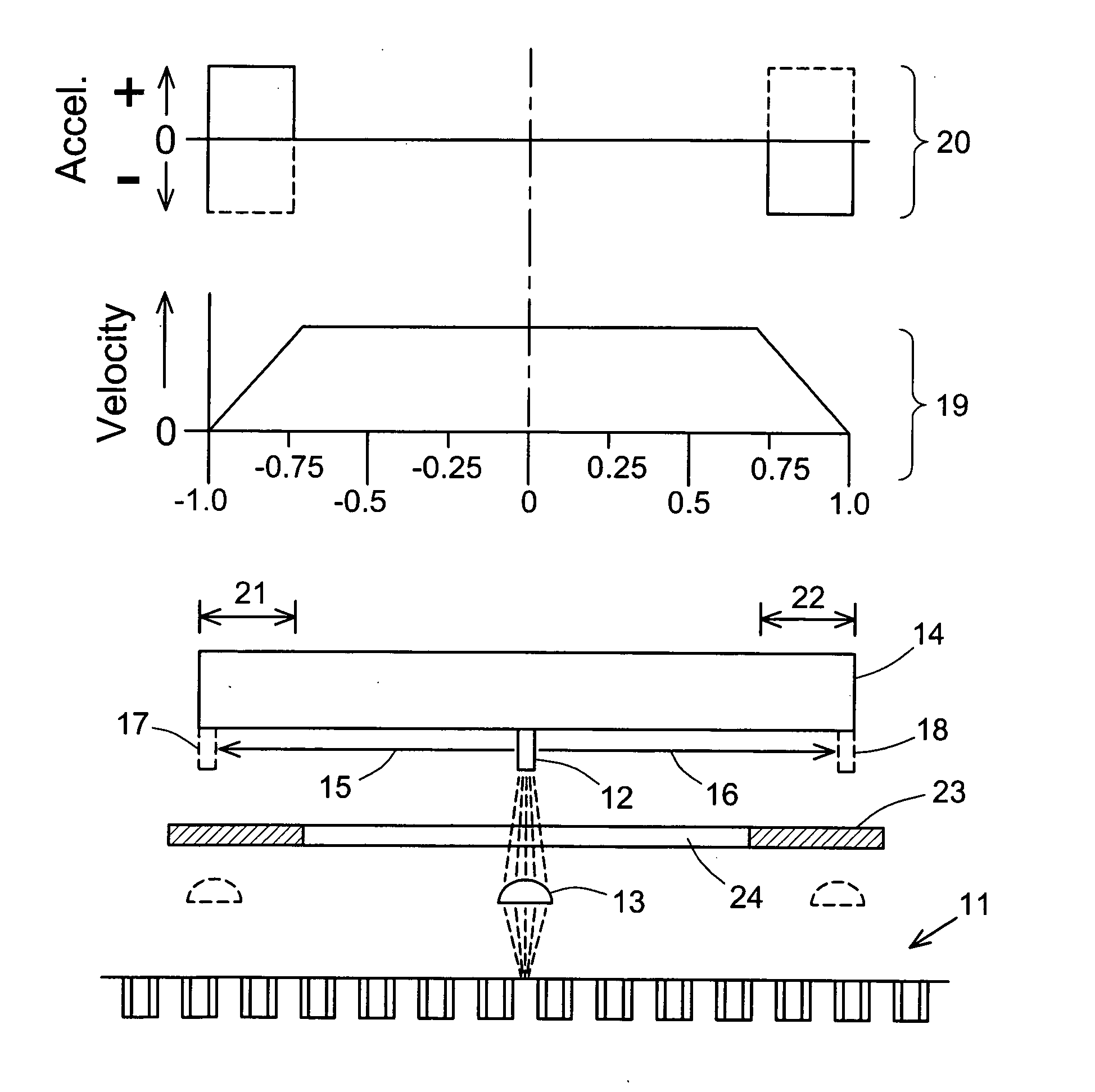
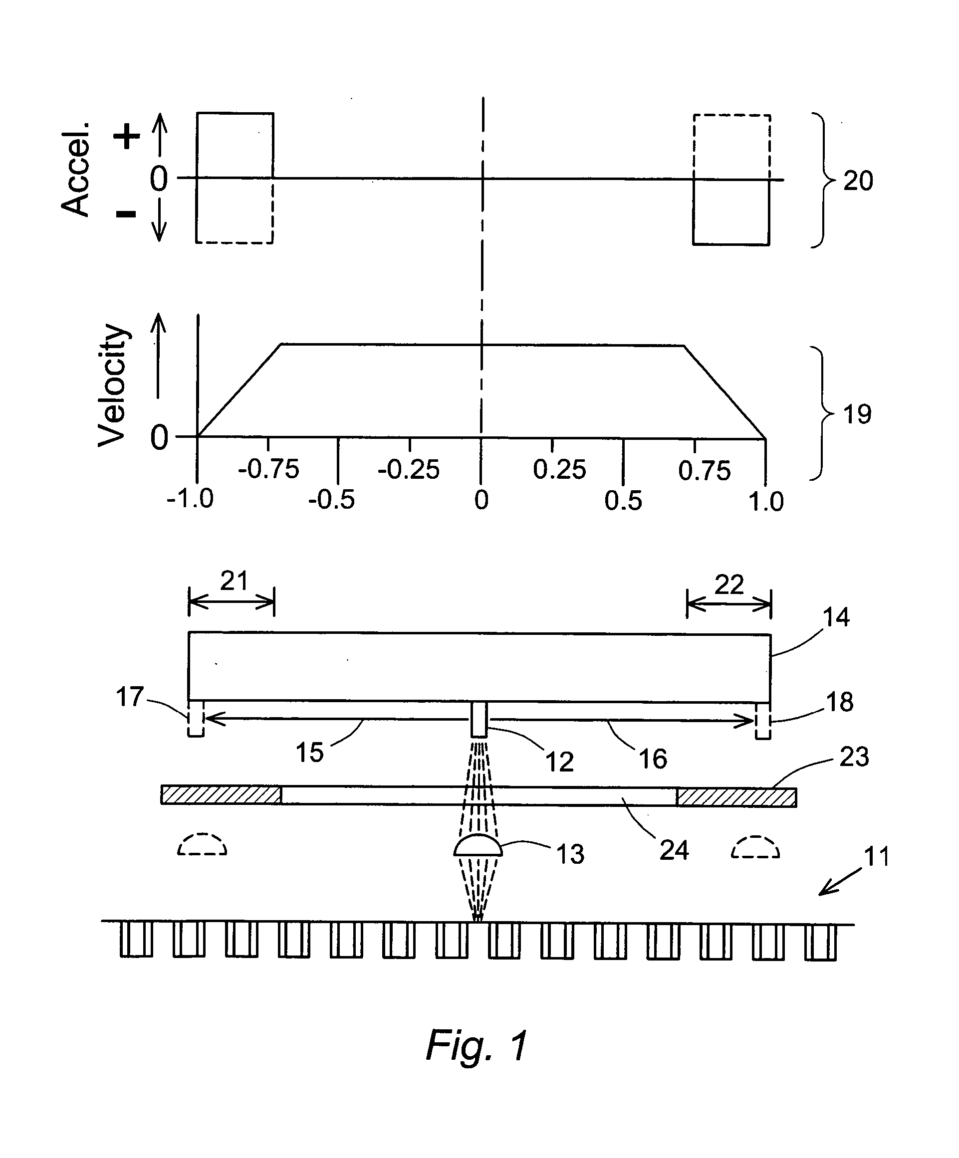
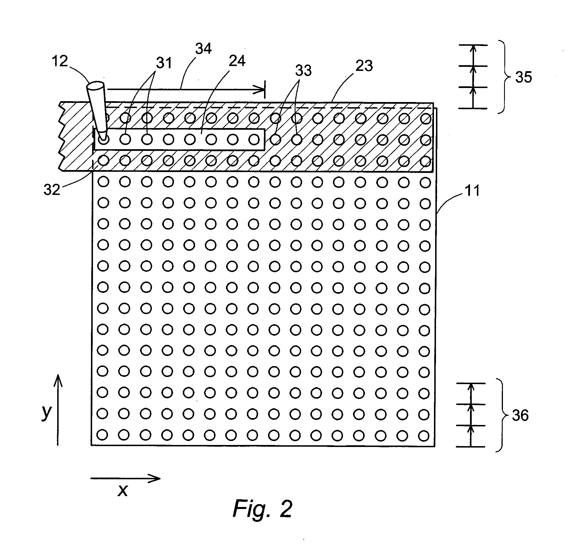
[0006] These and other limitations of the prior art are addressed by the present invention, which resides in a microarray scanning illumination system that includes a sample support, a reciprocating-motion scan head, and a mask positioned between the sample support and the scan head, the mask blocking all light from passing from the scan head to the sample support other than through an opening in the mask that exposes only the sites to be scanned in a single stroke of the scan head or a series of parallel strokes. Defining the scanning direction along a single row as the x-axis, the width of the opening parallel to the x-axis in certain embodiments of the invention is sufficient to expose more than one, but less than all, of the sample sites in a row, and is shorter in length than the path of travel of the scan head in a single stroke of the reciprocating movement of the scan head. With the mask appropriately sized and positioned, light from the scan head will be blocked and thus prevented from reaching the microarray at the two ends of the path of travel where the scan head is decelerating or accelerating to reverse its direction. In certain embodiments as well, the mask can also be sized and positioned to expose only one row, or a portion of only one row, of sites in the microarray, thereby preventing spillage of light onto adjacent rows. The mask is particularly useful when the scan head traverses only a portion of a row in a single stroke but can be shifted to another portion or the remainder of the row at a later stage of the imaging process to complete a scan of the entire row. In general, the present invention resides in the use of the mask to prevent the unwanted illumination of sites not being scanned, or to prevent nonuniform exposure of sites due to the end effects of the reciprocating motion of the scan head, or to prevent both. In all cases, the mask is movable relative to the microarray, or vice versa, to expose different groups of sites to the scan head as needed to provide a complete scan of the microarray.

Problems solved by technology

If sites of the microarray extend to the ends of the path of travel of the scanner head, the use of an uninterrupted laser beam can cause certain sites to receive greater exposure than others.
This can lead to overexposure or photobleaching of the site contents.
In addition, regardless of whether the laser beam is left on continuously or turned off at the ends of each stroke, a certain degree of light spillage to adjacent wells occurs, either by diffusion, reflection or refraction, when the laser is focused on any single well.
Light spillage of this nature can occur between rows as well as within a row, particularly when the path of travel of the scanner head exceeds the width of the row.
Light spillage can also occur when a single stroke covers only a portion of a row, with spillage onto portions of the row that are not being scanned.
In all cases, the spillage causes undesirable overexposure or generates background noise among the scanning signals, or both.

Method used


Image

  • Masking to prevent overexposure and light spillage in microarray scanning
  • Masking to prevent overexposure and light spillage in microarray scanning
  • Masking to prevent overexposure and light spillage in microarray scanning

Examples


Embodiment Construction

[0011] The sequence in which the sites of the microarray are illuminated by the light source during the scanning process path is referred to herein as the scanning protocol, and is determined by the length of each stroke of the scan head (to which the light source is affixed) during the reciprocating, i.e., back-and-forth, motion of the scan head, in conjunction with the incremental movements of the microarray to align the scan head with successive rows of sample sites on the microarray and all other movements of the scan head, mask, and microarray needed to complete the scanning of the entire microarray. While individual protocols can vary depending on the configuration and dimensions of the microarray, all protocols will include reciprocating motion of the scan head along the x-axis for each row of the microarray. While a uniform scan head speed would provide the most even distribution of illumination among the sample sites along the path of travel, absolute uniformity is not achi...


PUM


Abstract

Scanning of a microarray is performed through a mask that exposes a plurality, but not all, of the sites of the microarray, and either the mask is movable relative to the microarray or the microarray is movable relative to the mask, or both. The mask is useful as a means of restricting the illumination of sites on the microarray to those that can be illuminated while the scan head is traveling at a steady, target velocity, blocking the passage of light between the scan head and the microarray at those points in the scan head trajectory where the scan head is either accelerating or decelerating. The mask is also useful for reducing background noise in the microarray image by preventing light spillage to sites adjacent to those being scanned.

Description

BACKGROUND OF THE INVENTION [0001] 1. Field of the Invention [0002] This invention relates to scanning systems for microarrays of biological species such as nucleic acids and proteins, and in general to illumination systems for any type of procedure that involves the individual and sequential illumination of a large number of sites arranged in a spatial array. [0003] 2. Description of the Prior Art [0004] Microarrays are two-dimensional arrays of sites where chemical or biochemical assays are performed, each site often being of microscopic dimensions, with an independent assay and often a different molecular species at each site. Microarrays are formed on a variety of substrates, including glass slides, microtiter plates, and membranes. Microarrays are commonly used for example in binding assays for identifying, determining the binding affinity of, or otherwise characterizing unknown biological species. The size, number and spacing of the sites in a microarray can vary considerably....

Claims


Application Information

Patent Timeline
Patent Type & Authority Applications(United States)
IPC IPC(8): B41J15/14
CPCG01N21/253G01N2201/0446G01N2201/1042
Inventor CHU, DANIEL Y.
Owner BIO RAD LAB INC
Learn More