Projection display apparatus

a projection display and display technology, applied in the direction of projectors, mountings, instruments, etc., can solve the problems of heavy weight of the projection lens barrel used in the projection display apparatus, easy to loosen the mount ring, and break the screw thread of the screw

Active Publication Date: 2007-06-14
MITSUBISHI ELECTRIC CORP
View PDF2 Cites 11 Cited by
  • Summary
  • Abstract
  • Description
  • Claims
  • Application Information

AI Technical Summary

Benefits of technology

[0009] The present invention aims to provide a projection display apparatus in which the mounting ring is from being tightened in excess, and in which loosening of the mount ring is easily prevented.

Problems solved by technology

However, in the bayonet type, the worker tends to tighten the mount ring in excess to ensure attachment, thereby breaking the screw thread of the screw coupling part of the mount ring and the projection display apparatus.
In particular, the weight of the projection lens barrel used in the projection display apparatus is heavy since a lens of large aperture must be used to increase the lighting of the projecting image, and thus the worker is further motivated to tighten the mount ring more strongly.
In Japanese Patent Application Laid-Open No. 2004-54040 (see abstract etc), a configuration of preventing the mount ring from loosening is disclosed, but the prevention of the turning of the mount ring and the release thereof is performed by removing the lens hood, and thus the work becomes troublesome since the lens hood must be removed each time the projection lens barrel is to be removed.

Method used


Image

  • Projection display apparatus
  • Projection display apparatus
  • Projection display apparatus

Examples


Embodiment Construction

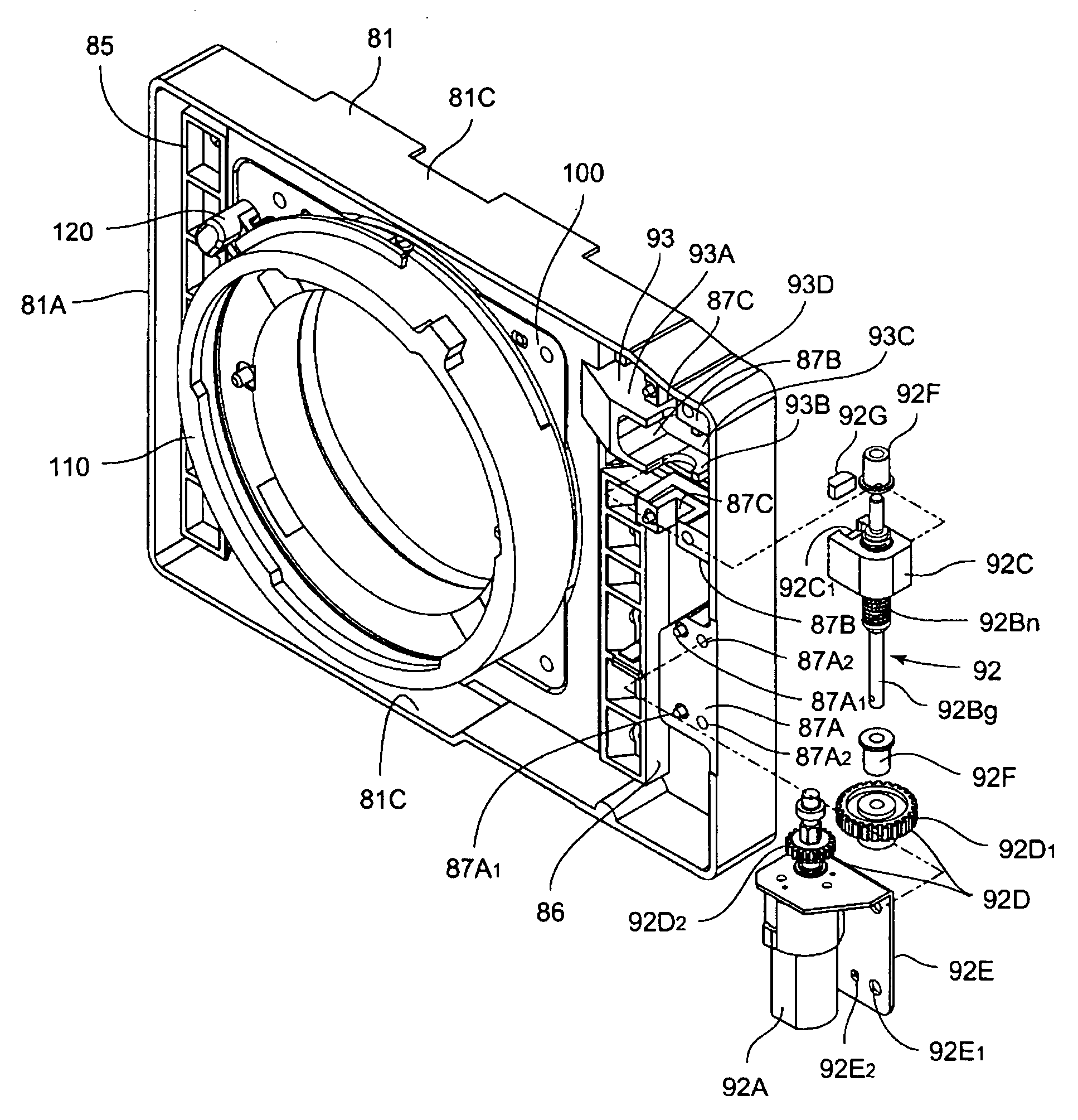
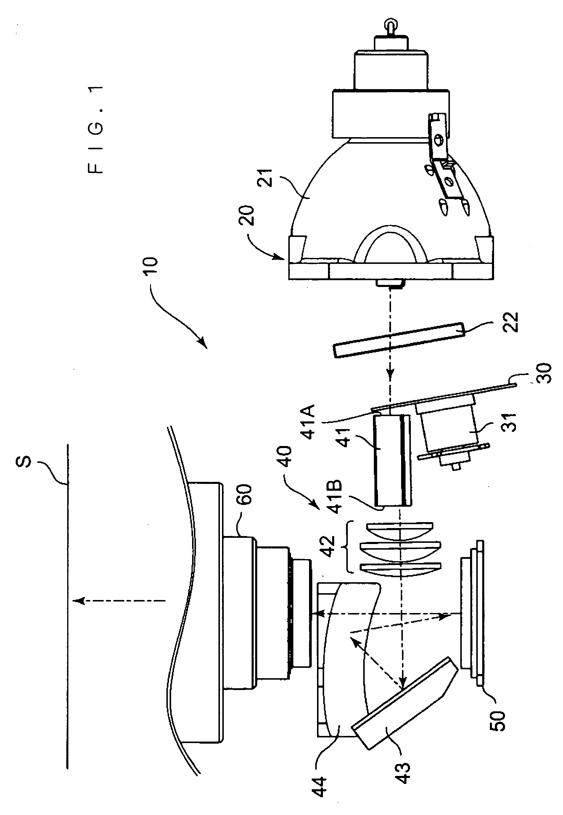
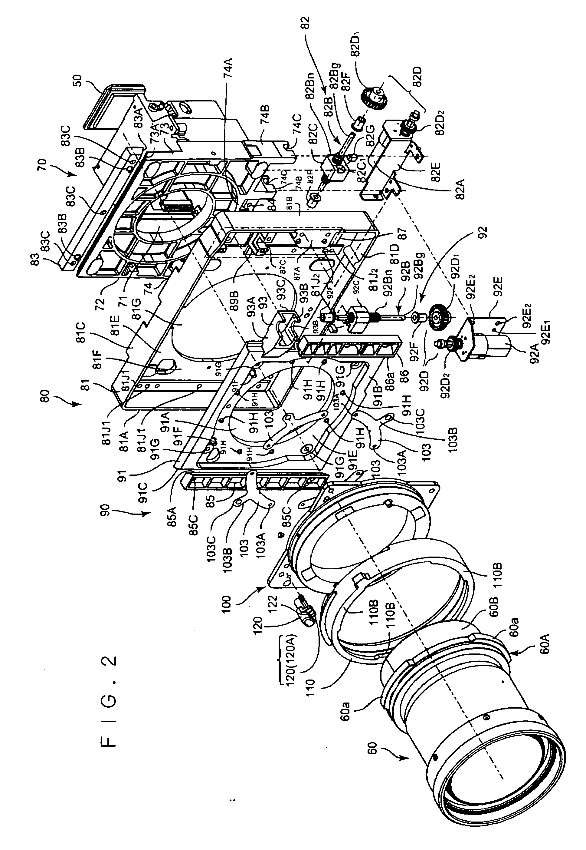
[0020] The embodiments of the projection display apparatus according to the present invention will now be described with reference to FIGS. 1 to 4, FIGS. 5A and 5B, FIGS. 6A to 6C and FIGS. 7A to 7C. A projection display apparatus including a micromirror display device as a light modulating element is described as the projection display apparatus by way of example in the present embodiment, but is not limited thereto, and may be other types of projection display apparatus such as a so-called liquid crystal projector etc. that uses a liquid crystal display device as the light modulating element. The micromirror display device is a light modulating device in which a large number of square micromirrors each having some μm side are arranged on a silicon substrate, inclination of the micromirrors is changed utilizing electrostatic attraction, thereby controlling whether light from a light source should be reflected in a direction of a screen. This micromirror display device generally has...


PUM


Abstract

The projection display apparatus includes rotation regulating elements for inhibiting a rotation of the mount ring in a tightening direction, and a stopper element displaceable between a non-locked position and a locked position, wherein the stopper element is displaced to the non-locked position when the mount ring is rotated to a rotating position in a loosening direction from a predetermined position in the tightening direction, and is displaced to the locked position when the mount ring is rotated to the predetermined position in the tightening direction.

Description

BACKGROUND OF THE INVENTION [0001] 1. Field of the Invention [0002] The present invention relates to a projection display apparatus in which a projection lens barrel is capable of being interchanged. [0003] 2. Description of the Background Art [0004] The projection display apparatus configured so that the lens barrel is selected and interchanged according to the size of the screen or the distance to the screen is being widely used. In such a projection display apparatus, a so-called bayonet type is sometimes adopted for the attachment part with respect to the projection lens barrel in terms of facilitating the removal and ensuring the reliability of attachment. [0005] The bayonet type is configured so that a bayonet flange arranged on the projection lens barrel side is sandwiched between the nail part of a mount ring to be screw coupled to the side of the projection display apparatus and the mounting surface, and the mount ring is rotated about the screw coupling part to be tightene...

Claims


Application Information

Patent Timeline
Patent Type & Authority Applications(United States)
IPC IPC(8): G03B21/14G02B7/02
CPCG02B7/14G02B15/04G03B21/14G03B21/142
Inventor KUROKI, FUTOSHIIWAI, TOSHIMITSUKIDA, HIROSHI
Owner MITSUBISHI ELECTRIC CORP
Why Eureka
Try Eureka