Magnetic storage device and method of correcting magnetic head position

Inactive Publication Date: 2007-06-14
TOSHIBA STORAGE DEVICE CORP
View PDF24 Cites 5 Cited by
  • Summary
  • Abstract
  • Description
  • Claims
  • Application Information

AI Technical Summary

Benefits of technology

[0014] According to the present invention, as described above, the head position is corrected based on track deviation information read from a storage unit that stores the information of the track deviation due to an abnormal pitch of a servo tr

Problems solved by technology

However, at the time of writing a servo pattern into a disc, a track can have an uneven track pitch in some cases.
This track-pitch deviation occurs when a voice coil motor that moves the write head to write the servo pattern does not rotate satisfactorily, or when a push pin that moves the head to be used by a servo track writer is contacted unsatisfactorily, or when an environmental oscillation or shock occurs

Method used


Image

  • Magnetic storage device and method of correcting magnetic head position
  • Magnetic storage device and method of correcting magnetic head position
  • Magnetic storage device and method of correcting magnetic head position

Examples


Example

EXAMPLE 1

Writing of Data Into Track 4

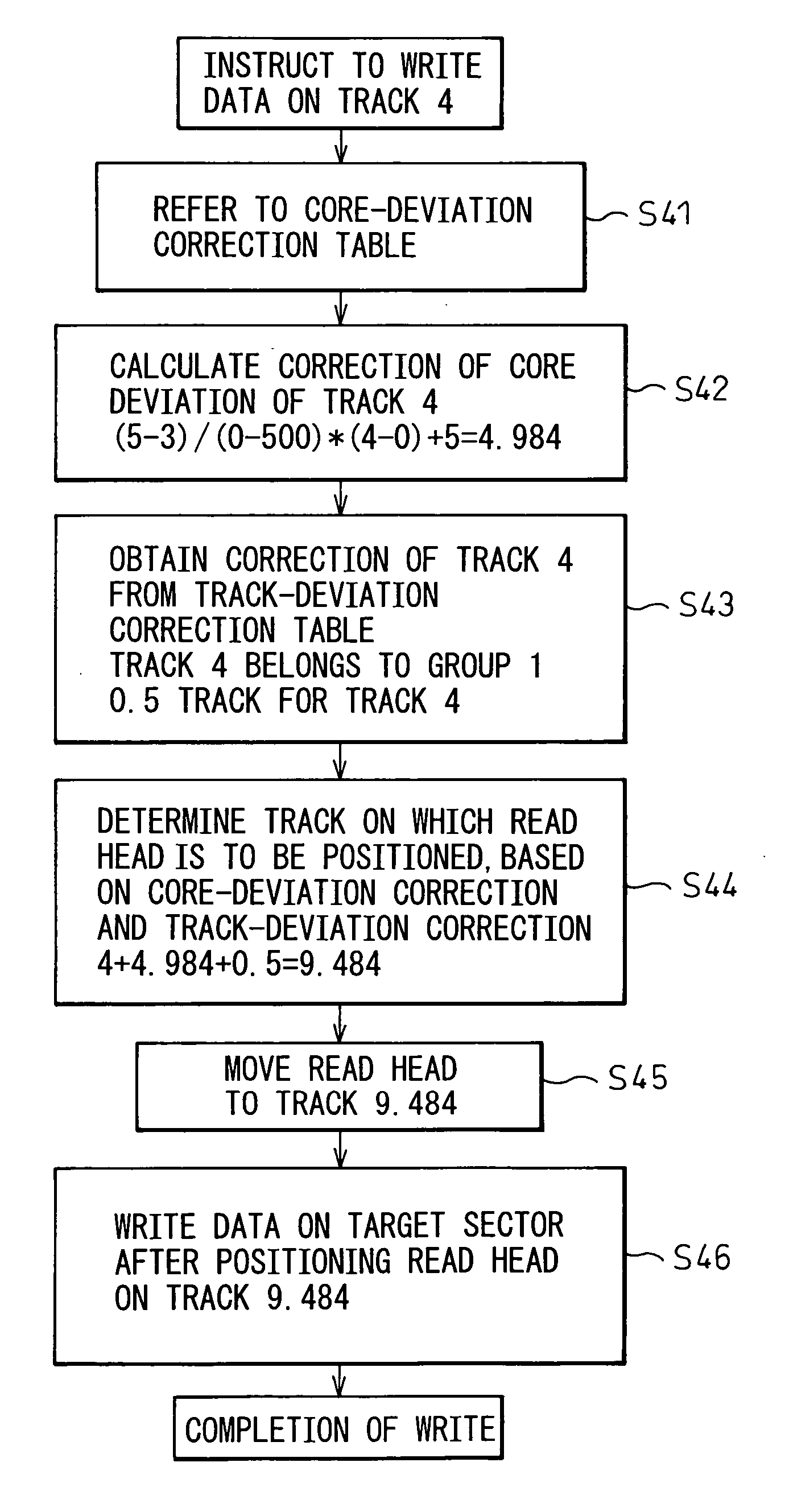
[0083]FIG. 6 shows an operation flow for writing data on track 4. When an instruction to write data on track 4 is given, the core-deviation correction table (FIG. 4A) is first referred to obtain the correction of core deviation of track 4 (step S41). The core-deviation correction table is stored in a nonvolatile memory such as a flash memory or a system region of a hard disc. Track 4 is not registered in the core-deviation correction table. Therefore, the correction of core deviation of track 4 is obtained by a linear interpolation (step S42).

[0084] In other words, track 4 is positioned between track 0 and track 500. The correction of core deviation of track 0 is five tracks, and the correction of core deviation of track 500 is three tracks. Therefore, the correction of core deviation of track 4 is obtained as follows.

[(5−3) / (0−500)]×(4−0)+5=4.984

[0085] Next, the correction of track deviation of track 4 is read from the track-deviation correcti...

Example

EXAMPLE 2

Data Reading From Track 4

[0088]FIG. 7 shows an operation flow for reading data from track 4. Unlike the data write operation, the data read operation does not require correction of core deviation. Therefore, when a data read instruction is given, the track-deviation correction table is referred to. Then a group number corresponding to track 4 is read from the track-deviation correction table (FIG. 4B) (step S51). Track 4 corresponds to group 1.

[0089] Next, correction of track deviation is calculated, and a track on which the read head is to be positioned is calculated. In this case, track 4 belongs to the group 1 and there is clearly no group that requires correction of track deviation before the group 1. Therefore, the correction of track deviation is zero (step S52).

[0090] Consequently, the read head is moved to track 4, without requiring correction of track deviation (step S53), and data is read from a sector of the target track after the read head is positioned on tr...

Example

EXAMPLE 3

Data Writing Into Track 7

[0091]FIG. 8 shows an operation flow for data writing into track 7. When an instruction to write data on track 7 is given, the core-deviation correction table (FIG. 4A) is first referred to obtain the correction of core deviation of track 4 (step S71). Track 7 is not registered in the core-deviation correction table. Therefore, the correction of core deviation is obtained by a linear interpolation (step S72).

[0092] In other words, track 7 is positioned between track 0 and track 500. The correction of core deviation of track 0 is five tracks, and the correction of core deviation of track 500 is three tracks. Therefore, the correction of core deviation of track 7 is obtained as follows.

[(5−3) / (0−500)]×(7−0)+5=4.972

[0093] Next, the correction of track deviation of track 7 is read from the track-deviation correction table (FIG. 4B) (step S73). The correction of track deviation of track 7 is the deviation 0.5 track of the group 1, because track 7 is in...


PUM


Abstract

A head position is corrected based on track deviation information read from a storage unit that stores the information on track deviation due to an abnormal pitch of a servo track. At the time of writing data, a track on which a read head R is to be positioned, which is determined based on correction of core deviation of a write head, is further corrected based on correction of track deviation information.

Description

BACKGROUND OF THE INVENTION [0001] 1. Field of the Invention [0002] The present invention relates to a magnetic storage device and, more particularly, to a magnetic storage device that corrects track-pitch deviation. [0003] 2. Description of the Related Art [0004] In general, a magnetic storage device or a magnetic disc device uses a write head to record data or information into a magnetic disc as a storage medium, and uses a read head to reproduce the recorded data or information. In recent years, most magnetic storage devices have a write head and a read head combined each other, instead of using one head to read and write data. When the writes head writes data on a disc, a read head is used to read position information or servo information, which is written in advance in a magnetic disc as a servo pattern. Based on the read servo information, the write head is positioned on a predetermined track, and writes data on the track, thereby preventing data from being written on adjacent...

Claims


Application Information

Patent Timeline
IPC IPC(8): G11B5/596
CPCG11B5/59627
Inventor ISHII, KOJI
Owner TOSHIBA STORAGE DEVICE CORP
Why Eureka
Try Eureka