Scheduling apparatus and method in channel bonding transmission system

a transmission system and channel bonding technology, applied in electrical equipment, digital transmission, data switching networks, etc., can solve the problems of increasing transmission delay time between packets, difficult to expect the increase of transfer rate, and increasing transmission delay between packets, which are simultaneously transmitted through a plurality of channels

Inactive Publication Date: 2007-06-14
ELECTRONICS & TELECOMM RES INST
View PDF5 Cites 39 Cited by
  • Summary
  • Abstract
  • Description
  • Claims
  • Application Information

AI Technical Summary

Problems solved by technology

Therefore, it is difficult to expect the increase of transfer rate according to the number of the bonded channel as shown in Tables 1 and 2.)
There is a problem that a transmission delay time between packets, which are simultaneously transmitted through a plurality of channels, may increase according to the status of each channel

Method used


Image

  • Scheduling apparatus and method in channel bonding transmission system
  • Scheduling apparatus and method in channel bonding transmission system
  • Scheduling apparatus and method in channel bonding transmission system

Examples


Embodiment Construction

[0023] Other objects and advantages of the present invention will become apparent from the following description of the embodiments with reference to the accompanying drawings. Therefore, those skilled in the art that the present invention is included can embody the technological concept and scope of the invention easily. In addition, if it is considered that detailed description on a related art may obscure the points of the present invention, the detailed description will not be provided herein. The preferred embodiments of the present invention will be described in detail hereinafter with reference to the attached drawings.

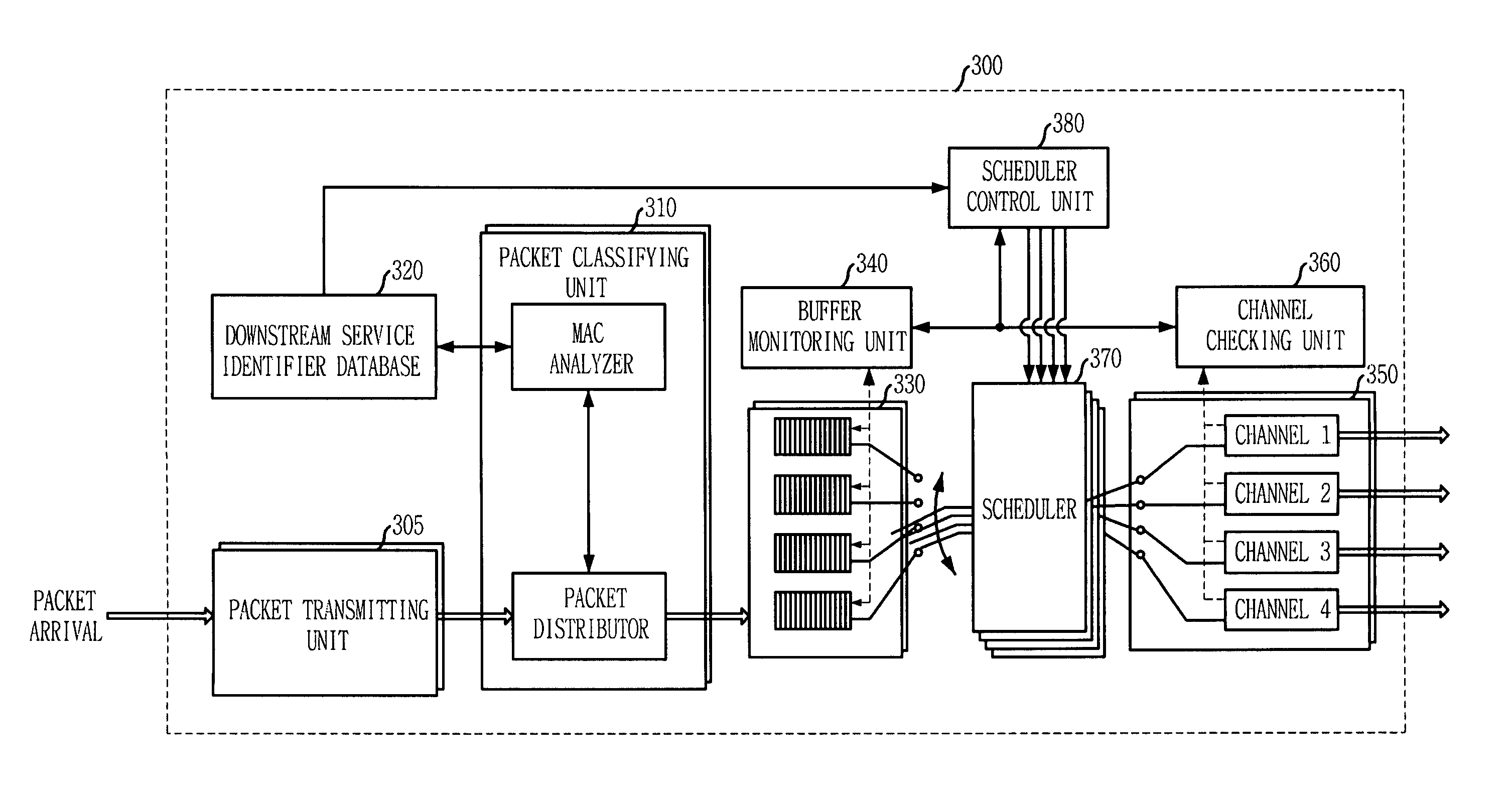
[0024]FIG. 3 is a block diagram showing a scheduling apparatus in a channel bonding transmission system in accordance with an embodiment of the present invention. The scheduling apparatus in the channel bonding transmission system of the present invention includes a downstream service identifier database 320, a packet Forwarder unit 305, a packet Distributor u...


PUM


Abstract

Provided is a scheduling apparatus and method in a channel bonding transmission system. The apparatus includes: a downstream service identifier storing unit for storing information related to a downstream service identifier (DSID); a packet transmitting unit for transmitting a packet inputted from outside; a packet classifying unit for analyzing the packet and distributing the downstream service identifier; a virtual storing unit for storing the packets by the packet classifying unit; a monitoring unit for checking downstream service identifier information of the packet stored in the virtual storing unit and requesting channel distributing and channel holding; a channel checking unit for checking the status of channels; a scheduling control unit for acquiring channel information from the downstream service identifier storing unit and controlling packet forwarding; a scheduling unit for forwarding the packets; and an output unit for outputting the forwarded packets.

Description

FIELD OF THE INVENTION [0001] The present invention relates to a scheduling apparatus and method that can efficiently transmit data by channel bonding in conformity to the Data Over Cable Service Interface Specifications (DOCSIS) 3.0 standard for providing an interactive high-speed data service in a cable network. DESCRIPTION OF RELATED ART [0002] The Data Over Cable Service Interface Specifications (DOCSIS) standard is established in CableLabs to provide an interactive high-speed data service in a cable network. A current DOCSIS 2.0 standard provides a transmission speed of about 30 Mbps (6.4M, 64 QAM) in upstream transmission and about 42 Mbps (6 MHz, 256 QAM) in downstream transmission. A DOCSIS 3.0 standard for increasing a transmission bandwidth through channel bonding is being developed to provide diverse services and improve a transmission speed. A transmission speed according to the number of the bonded channel is as shown in Tables 1 and 2 below. [0003]FIG. 1 shows a channe...

Claims


Application Information

Patent Timeline
Patent Type & Authority Applications(United States)
IPC IPC(8): H04L12/28H04L12/56
CPCH04L47/10H04L47/2441
Inventor KWON, HO-JINKWON, O-HYUNGLEE, SOO-IN
Owner ELECTRONICS & TELECOMM RES INST
Why Eureka
Try Eureka