Method and apparatus for channel bonding using a multiple-beam antenna

a multi-beam antenna and channel bonding technology, applied in diversity/multi-antenna systems, digital transmission, polarisation/directional diversity, etc., can solve the problems of limiting channel frequency choices, communication failures or excessively high error rates, network interface cards on host computers, etc., to improve throughput and reliability of wireless communications, reduce interference and multi-path effects, and increase data bandwidth

Active Publication Date: 2008-11-27
SPATIAL DIGITAL SYST
View PDF5 Cites 24 Cited by
  • Summary
  • Abstract
  • Description
  • Claims
  • Application Information

AI Technical Summary

Benefits of technology

[0009]A system is provided that enhances the throughput and reliability of wireless communications by providing multi-beam user terminals that exhibit directional discrimination. Multiple wireless communication cha

Problems solved by technology

A network interface card on a host computer, for example, may be limited to a certain maximum data rate.
When channel bonding is attempted over wireless networks, interference between the multiple wireless network cards can cause communication failures or excessively high error rates.
However, of the eleven channels in the 2.4-GHz frequency band of the IEEE 802.11 b and g wireless standards, only channels 1 and 11 are spaced sufficiently far apa

Method used


Image

  • Method and apparatus for channel bonding using a multiple-beam antenna
  • Method and apparatus for channel bonding using a multiple-beam antenna
  • Method and apparatus for channel bonding using a multiple-beam antenna

Examples


Embodiment Construction

[0027]The invention provides a system for bonding multiple wireless communication channels using multi-beam directional antennas in order to improve communication bandwidth and reliability. In the detailed description that follows, like element numerals are used to indicate like elements appearing in one or more of the figures.

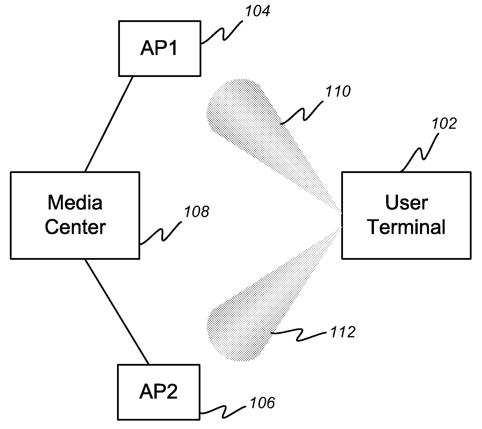
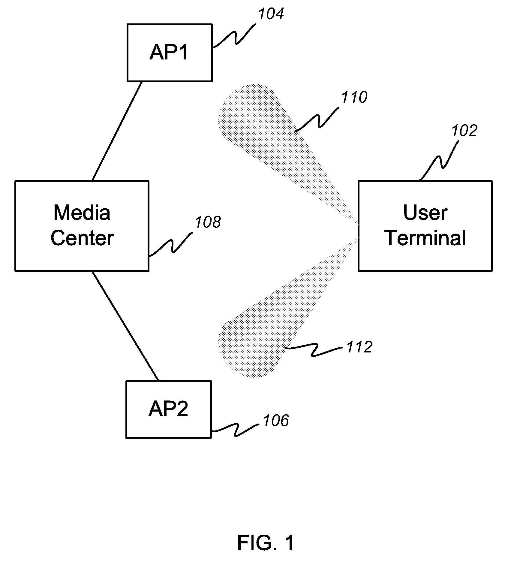
[0028]FIG. 1 depicts a block diagram of an embodiment of a multiple-beam wireless networking system in accordance with the present invention. A media center 108 stores data that it makes available to a wireless network over two spatially separated wireless access points 104 and 106. A user terminal 102 includes a multi-beam antenna capable of pointing narrow beams 110 and 112 in the directions to the two access points 104 and 106, respectively. The user terminal 102 includes a digital-beam-forming (DBF) processor described in more detail below with reference to FIG. 3. The DBF processor allows the construction of two spatially-separated beams that can be indep...


PUM


Abstract

A system is provided that enhances the throughput and reliability of wireless communications by providing multi-beam user terminals that exhibit directional discrimination. Multiple wireless communication channels are matched with multiple beams created from an array antenna by a beam-forming processor. The multiple wireless communication channels are bonded into a single virtual channel, thereby increasing data bandwidth while reducing interference and multi-path effects that can degrade communications. The beam-forming function may be performed in a dedicated beam-forming processor or may reside within a general-purpose microprocessor located in the user terminal.

Description

RELATED APPLICATION DATA[0001]This application claims the benefit, pursuant to 35 U.S.C. §119(e), of U.S. provisional application Ser. No. 60 / 930,958, filed May 21, 2007, and U.S. provisional application Ser. No. 60 / 930,957, filed May 21, 2007.BACKGROUND OF THE INVENTION[0002]1. Field of the Invention[0003]The present invention relates to techniques for improving the throughput and reliability of wireless links by bonding communication channels together. More particularly, the invention relates to techniques for using multi-beam antennas to communicate with spatially separated wireless access points that are then bonded to increase channel bandwidth.[0004]2. Description of Related Art[0005]It is well known in the art to increase the bandwidth and reliability of a communication interface by combining, or bonding, two or more sets of interface hardware. A network interface card on a host computer, for example, may be limited to a certain maximum data rate. A second network interface c...

Claims


Application Information

Patent Timeline
IPC IPC(8): H04L1/02
CPCH01Q1/2258H01Q1/2266H01Q25/00
Inventor CHANG, DONALD CHIN-DONG
Owner SPATIAL DIGITAL SYST
Why Eureka
Try Eureka