

Nuclear reactor internal structure
a technology of internal structure and nuclear reactor, which is applied in the direction of nuclear reactors, nuclear elements, greenhouse gas reduction, etc., can solve the problems of increasing the pressure loss in the flow of coolant b>1/b>, and achieve the effect of reducing the pressure loss of the flow of coolant and separating vortices
- Summary
- Abstract
- Description
- Claims
- Application Information
AI Technical Summary
Benefits of technology
Problems solved by technology
Method used
Image

Examples
first embodiment
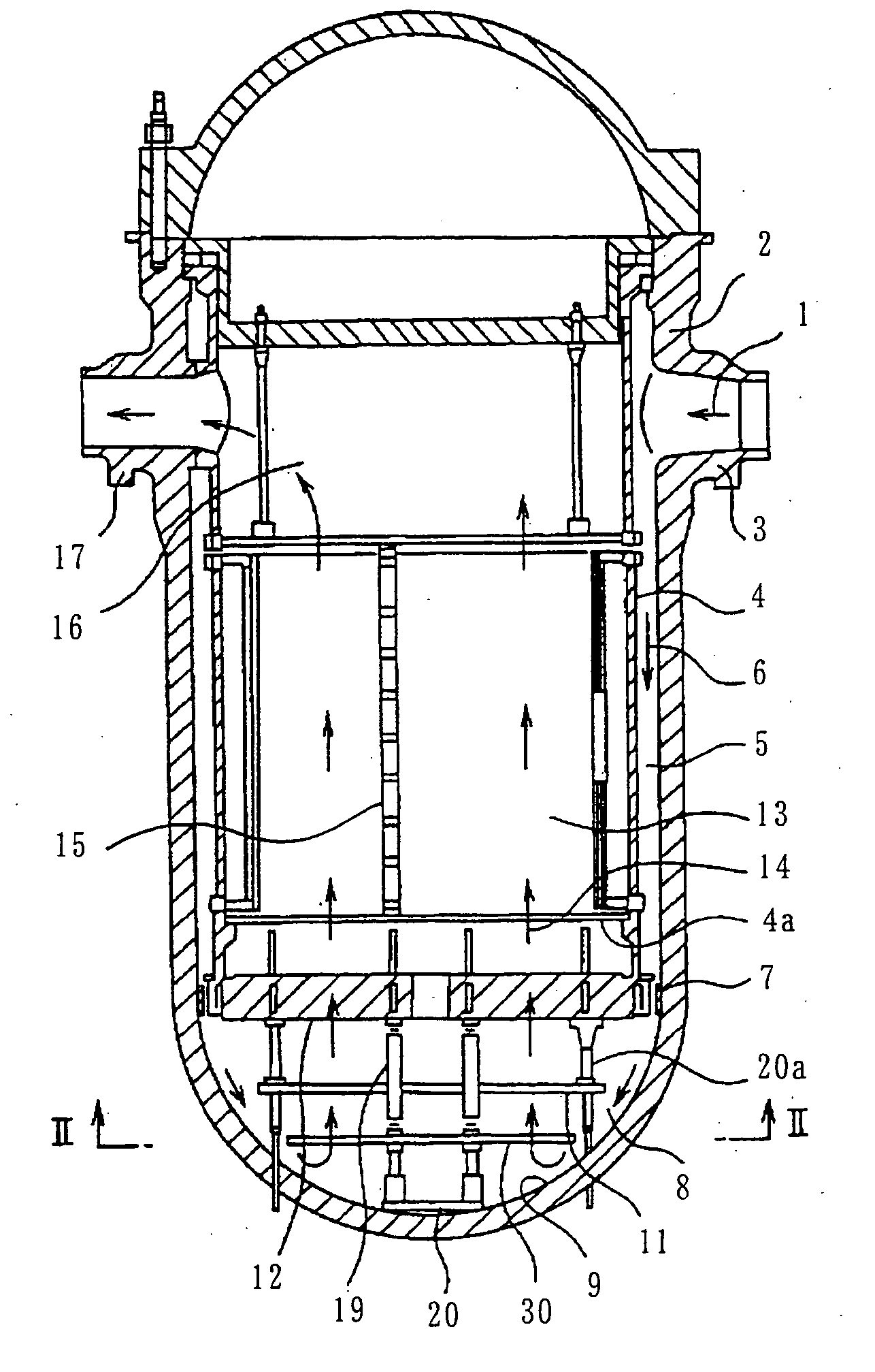
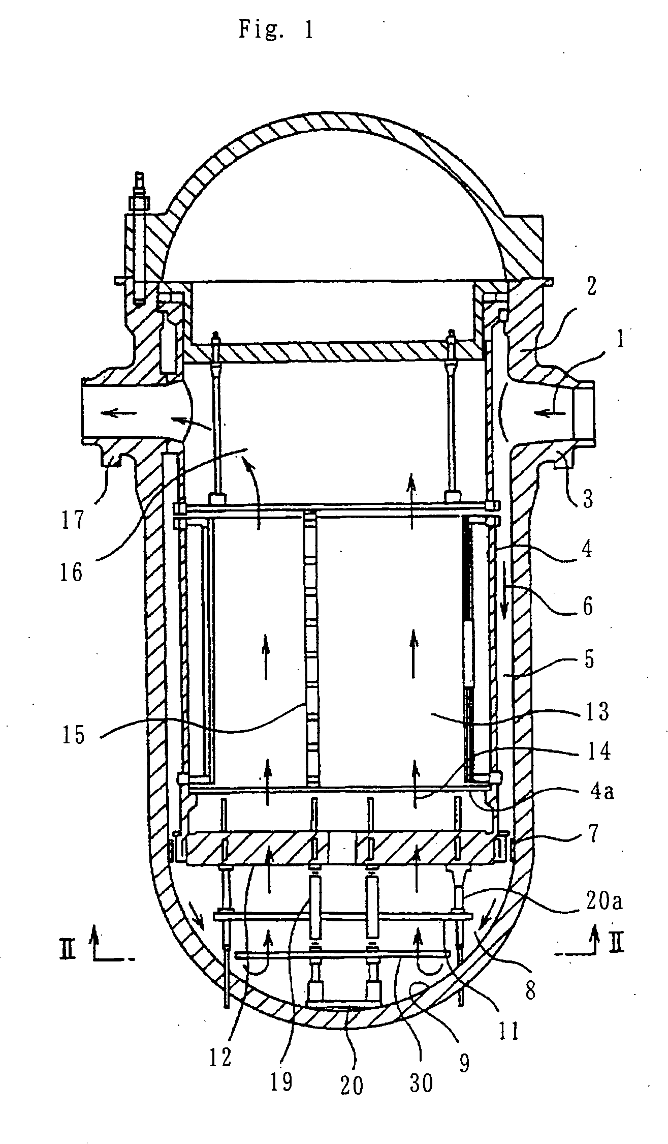
[0087]FIG. 1 is a longitudinal cross sectional view of a nuclear reactor internal structure of a first embodiment. This nuclear reactor relates to a pressurized water reactor and in this nuclear reactor internal structure, as compared with the prior art nuclear reactor internal structure shown in FIG. 19, a lower connecting plate 30 is provided in place of the conventional lower connecting plate 10.
[0088] In FIG. 1, the reactor vessel 2 as a pressure vessel has its upper opening closed by a detachable cover and the reactor core tank 4 is supported being suspended from a peripheral portion of the upper opening. The reactor core tank 4 has its bottom portion formed by the lower reactor core plate 4a of a flat plate shape and the reactor core 13 is provided with the fuel assembly 15 in which a multiplicity of fuel rods are arrayed on the lower reactor core plate 4a.
[0089] The downcomer portion 5 of an annular shape is provided between the reactor vessel 2 and the reactor core tank 4 ...
second embodiment
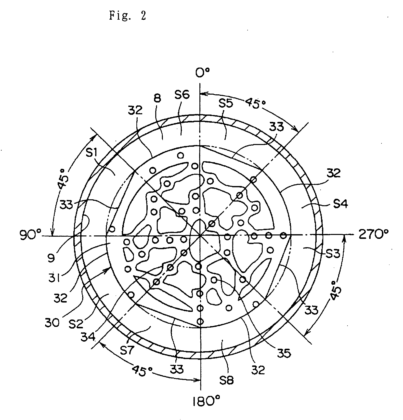
[0107] A second embodiment of a nuclear reactor internal structure according to the present invention has a lower connecting plate 40 provided therein in place of the lower connecting plate 30 employed in the first embodiment. As shown in FIG. 5, the lower connecting plate 40 is different from the lower connecting plate 30 shown in FIG. 2 only in the shape of the outer peripheral cut-off portion.
[0108] The cut-off portion 41 through which the main flow passes on the 90° axis side or the 270° axis side, as compared with the cut-off portion 42 through which the separating flow passes on the 0° axis side or the 180° axis side, is formed with an arcuate curve of the cut having a smaller radius as well as with a larger depth of the cut toward the center side of the lower connecting plate 40.
[0109] Also, both of the cut-off portions 41 and 42, as compared with the cut-off portion 33 that is linearly cut of the lower connecting plate 30 of FIG. 2, are formed with a larger depth of the cu...
third embodiment
[0112] A third embodiment of a nuclear reactor internal structure according to the present invention has a lower connecting plate 50 provided therein in place of the lower connecting plate 30 employed in the first embodiment. As shown in FIG. 6, the lower connecting plate 50 is different from the lower connecting plate 30 shown in FIG. 2 such that in the portion between the angles of 90° and 135° as well as of 270° and 315° of an outer periphery of a lower connecting plate main body 51 having none of the ring portion 31, a separating vortices suppressing member 52 as a plate-like member of an approximately T-shape having an arcuate outer periphery 52a is fixed to the lower connecting plate main body51 by welding, bolting or the like. Or, alternatively, the lower connecting plate 50 having its outer periphery formed with such a vortices suppressing member 52 may be made as an integral unit.
[0113] Thus, by so providing the vortices suppressing member 52 having the arcuate outer perip...
PUM
 Abstract
Description
Claims
Application Information