Eureka AIR delivers breakthrough ideas for toughest innovation challenges, trusted by R&D personnel around the world.

Diagnosis apparatus for diagnosing state of equipment

Inactive Publication Date: 2007-06-14
HITACHI LTD
View PDF5 Cites 12 Cited by
  • Summary
  • Abstract
  • Description
  • Claims
  • Application Information

AI Technical Summary

Benefits of technology

[0017] In the diagnosis apparatus for diagnosing state of equipment of the present invention, as it distinguishes the operation state, the operation environment, and the operation condition of the equipment, it estimates the state of the equipment based on the before and after relation of the time series information, and diagnoses the state of the equipment properly according to the estimated state, the diagnosis precision can be enhanced.

Problems solved by technology

However, as to an object such as a car with which it is difficult to decide in which state it is in only by looking at the time series information partly because a change point of the sate is not clear and the state of the equipment changes in various ways depending on operation environment and operation condition, there remains a problem in processing its time series information.

Method used


Image

  • Diagnosis apparatus for diagnosing state of equipment
  • Diagnosis apparatus for diagnosing state of equipment
  • Diagnosis apparatus for diagnosing state of equipment

Examples


Embodiment Construction

[0028] Next, an embodiment of the diagnosis apparatus for diagnosing state of equipment according to the present invention will be explained referring to FIG. 1-FIG. 9.

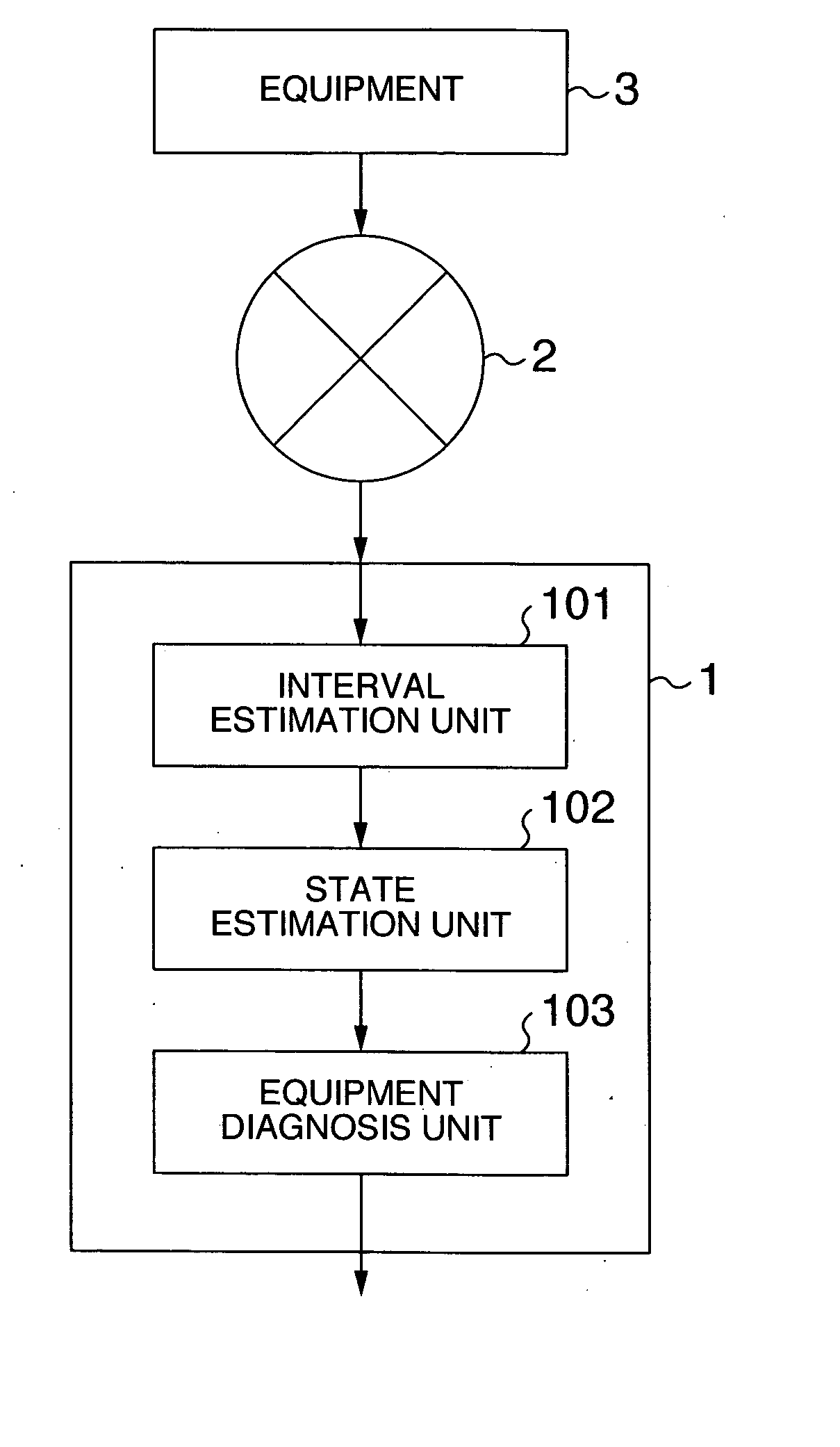
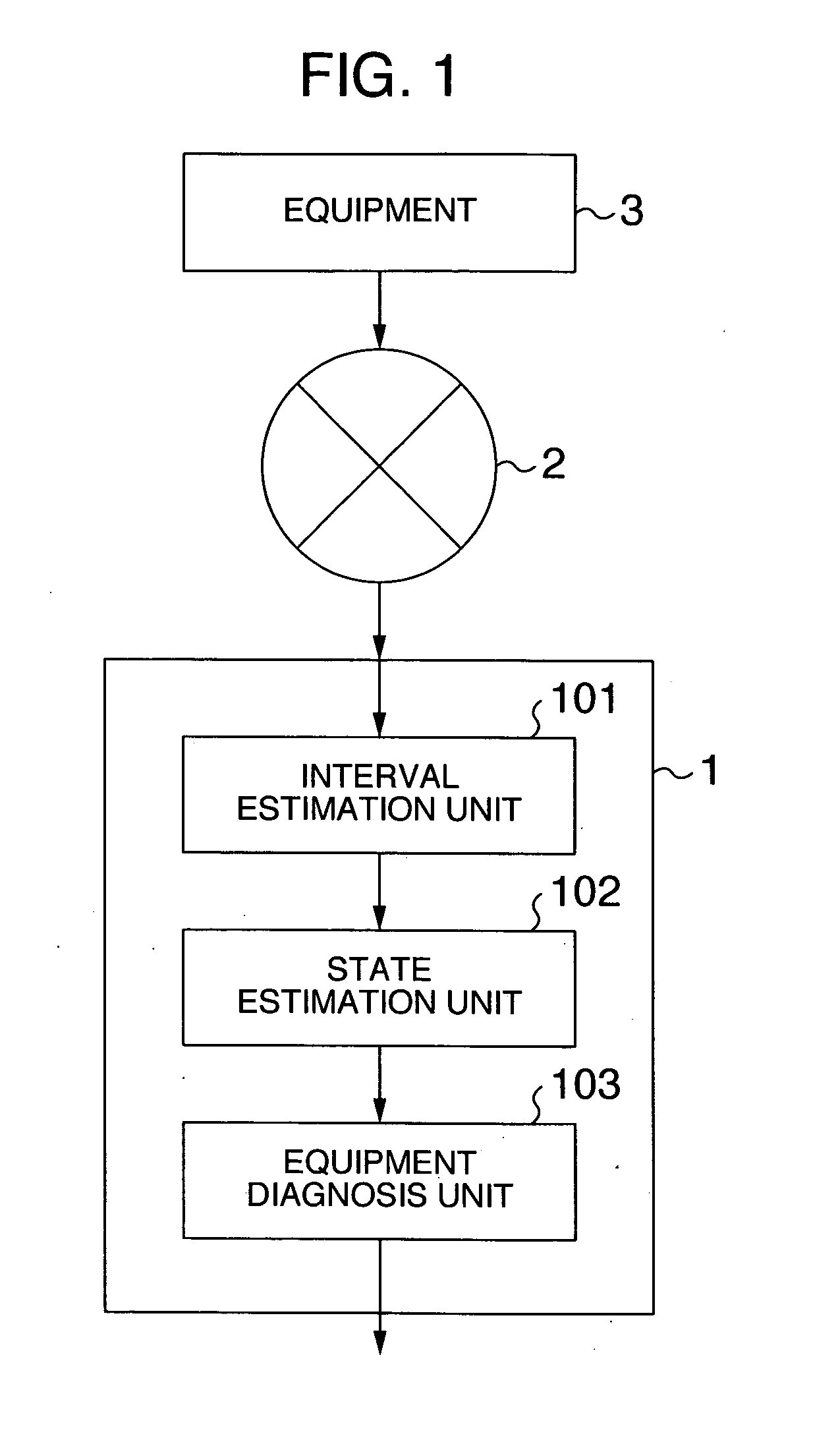
[0029]FIG. 1 is a block diagram showing a configuration of an embodiment of the diagnosis apparatus for diagnosing state of equipment according to the present invention.

[0030] A diagnosis apparatus for diagnosing state of equipment 1 receives time series information from diagnosis object equipment 3 via a network 2, diagnoses the state of the equipment 3, and outputs a result thereof. The time series information is a series of information which records state information such as a variety of kinds of control information and sensor information regarding the state of the equipment according to the time order.

[0031] For example, in the case of the car, data which records information such as a speed, a number of revolutions of engine, a degree of opening of accelerator, fuel consumption according to the time is the time...


PUM


Abstract

A diagnosis apparatus for diagnosing state of equipment includes an interval estimation unit which receives time series information from diagnosis object equipment and detects a change point of the time series information, a state estimation unit which receives the time series information from the diagnosis object equipment and change point information from the interval estimation unit, divides the time series information temporally with the change point as a boundary, and estimates a state of the equipment from before and after relation of an interval or relation with another time series information per divided interval, and an equipment diagnosis unit which diagnoses the equipment according to an estimated state.

Description

BACKGROUND OF THE INVENTION [0001] The present invention relates to a diagnosis apparatus for diagnosing state of equipment. [0002] In equipment for general use such as a car a mechanism to control and protect the equipment is provided within a control device of the equipment and when an abnormality is detected an alarm is displayed on a display panel, etc. to inform a user of the abnormality. [0003] Also, regarding the car, as regular inspections are obligatory by law a specialist diagnoses whether there is an abnormality or not at the inspection and if there is an abnormality the equipment is supposed to be repaired and maintained. [0004] Recently, there has been a proposition to provide a so-called drive recorder in a car body as a recording device similarly to a flight recorder in an airplane and to utilize its recorded data in a variety of forms (see, for example, JP-A-2002-073153 (pages 3, 4, FIG. 1-FIG. 4)). [0005] The recording device records such as how a driver operated at...

Claims


Application Information

Patent Timeline
IPC IPC(8): G01R29/02G01M99/00
CPCG05B23/0232
Inventor SUZUKI, HIDEAKIMIYAZAKI, TAIZOTANIKOSHI, KOICHIRO
Owner HITACHI LTD
Why Eureka
Eureka Blog
Learn More