Light receiving and emitting module and light receiving and emitting device

Pending Publication Date: 2022-05-19
CLOUD LIGHT TECH LTD
View PDF0 Cites 0 Cited by
  • Summary
  • Abstract
  • Description
  • Claims
  • Application Information

AI Technical Summary

Benefits of technology

[0013]According to the present disclosure, the light receiving and emitting module and light receiving and emitting device have advantages described below. The photoelectrical conversion component and lens are each disposed on the sub-mount platform which has small manufacturing tolerance, such that the alignment and optical coupling between the photoelectrical conversion component and lens is controlled effectively and precisely. The alignment between the photoelectrical conversion component and lens is not affected by the base whose

Problems solved by technology

If the overall tolerance is overly large, the light receiving and emitting module cannot couple with optical fiber, and thus the light signals cannot be correctly inputted to optical fiber or outputted from optical fiber.
Referring to FIG. 1, regardless of the magnitude of the tolerance, the intensity of the inp

Method used


Image

  • Light receiving and emitting module and light receiving and emitting device
  • Light receiving and emitting module and light receiving and emitting device
  • Light receiving and emitting module and light receiving and emitting device

Examples


Example

[0019]To facilitate understanding of the object, characteristics and effects of this present disclosure, embodiments together with the attached drawings for the detailed description of the present disclosure are provided.

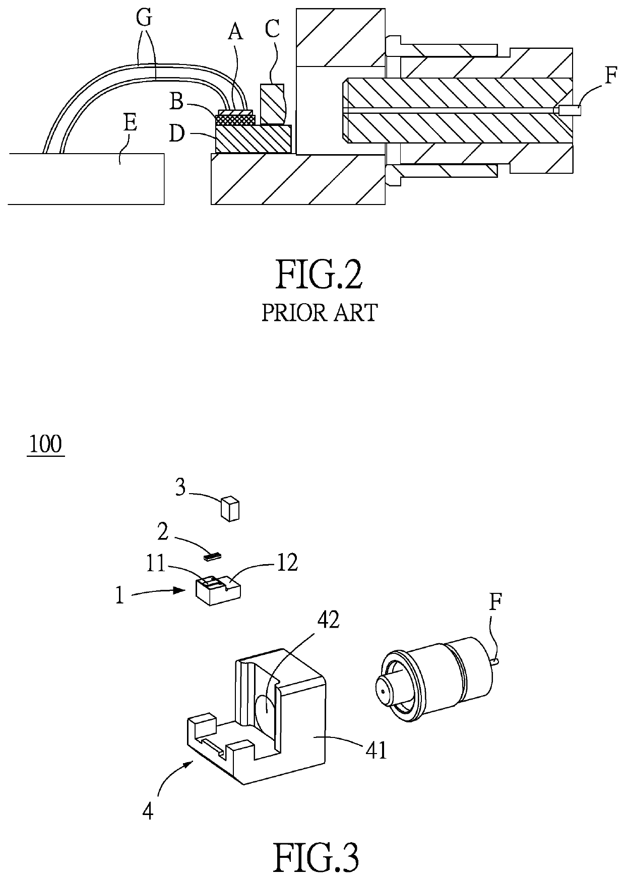
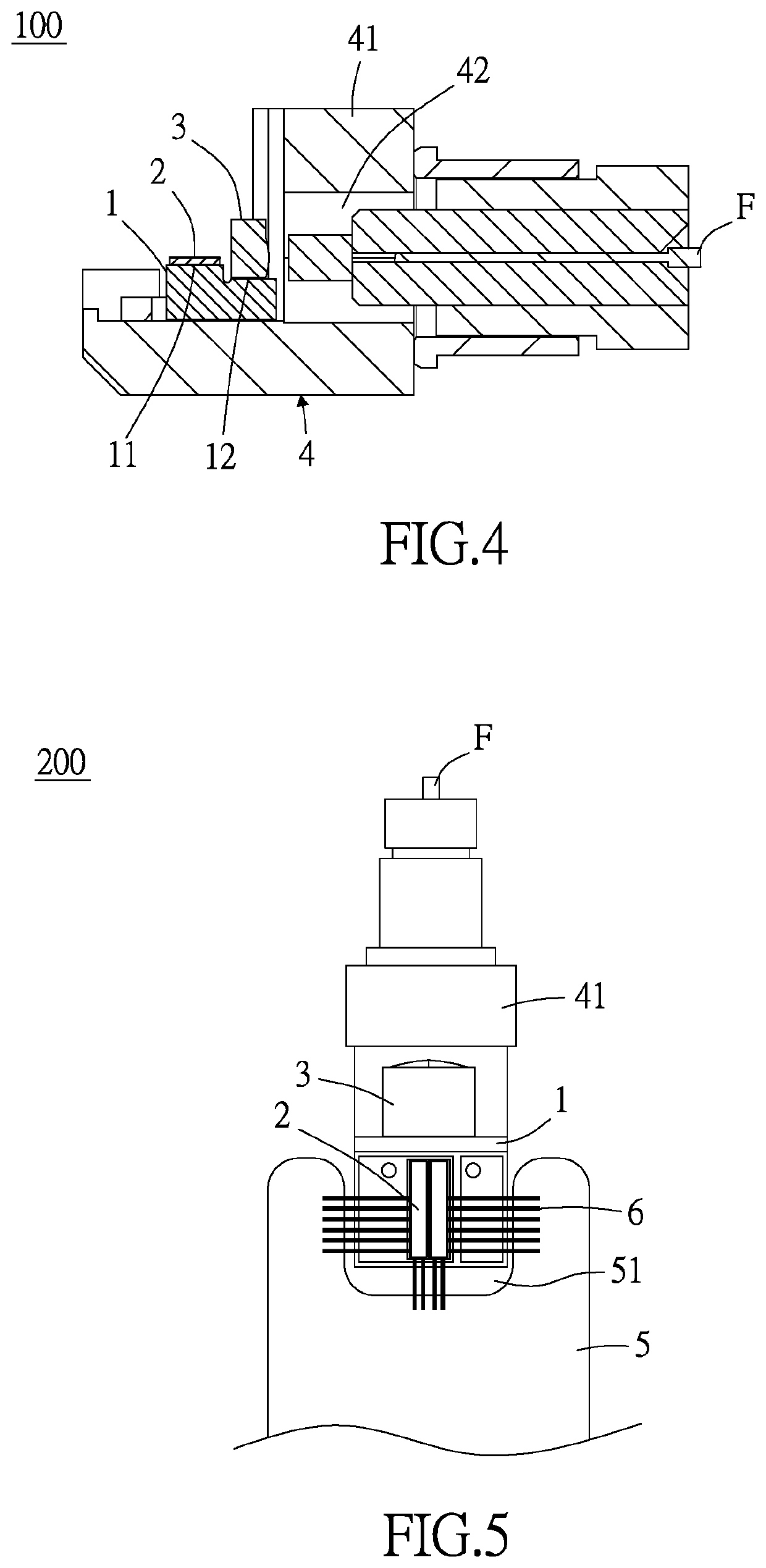
[0020]Referring to FIG. 3 and FIG. 4, in an embodiment of the present disclosure, a light receiving and emitting module 100 comprises a sub-mount platform 1, a photoelectrical conversion component 2, a lens 3 and a base 4.

[0021]The sub-mount platform 1 is made of a silicon-based material and manufactured by a semiconductor process to reduce manufacturing tolerance. Preferably, in this embodiment, the manufacturing tolerance of sub-mount platform 1 is controlled to fall within the range of + / −30 μm. The sub-mount platform 1 has a first contact surface 11 and a second contact surface 12 which photoelectrical conversion component 2 and lens 3 are disposed on, respectively.

[0022]The photoelectrical conversion component 2 is disposed on first contact surface 11. The phot...


PUM


Abstract

A light receiving and emitting module includes a sub-mount platform, a photoelectrical conversion component, a lens and a base. The sub-mount platform is made of silicon-based material and has first and second contact surfaces. The photoelectrical conversion component is disposed on the first contact surface. The lens is disposed on the second contact surface. The sub-mount platform is disposed on one side of the base. The first contact surface and second contact surface have therebetween a height difference, such that the photoelectrical conversion component matches the center of the lens. Further provided is a light receiving and emitting device including the light receiving and emitting module, a printed circuit board and a plurality of conducting wires. The conducting wires are electrically connected to the photoelectrical conversion component and printed circuit board. The conducting wires are disposed on at least two sides of the light receiving and emitting module.

Description

CROSS-REFERENCE TO RELATED APPLICATION[0001]This non-provisional application claims priority under 35 U.S.C. § 119(e) on U.S. provisional Patent Application No. 63 / 114,535 filed on Nov. 17, 2020, the entire contents of which are hereby incorporated by reference.BACKGROUND OF THE INVENTION1. Field of the Invention[0002]The present disclosure relates to light receiving and emitting modules and light receiving and emitting devices, and in particular to a light receiving and emitting module and a light receiving and emitting device which enhance optical coupling efficiency.2. Description of the Related Art[0003]Compared with cables, optical fibers manifest low energy loss rate in electrical signal transmission; thus, optical fibers, coupled with photoelectrical conversion components, are widely used in communications. Transmission of signals with a light receiving and emitting module requires a laser emitting member for converting electrical signals into light signals, and then the ligh...

Claims


Application Information

Patent Timeline
IPC IPC(8): G02B6/42
CPCG02B6/426G02B6/4204G02B6/4244G02B6/4245G02B6/424G02B6/428G02B6/4246G02B6/4274G02B6/423
Inventor HUANG, CHENG-KAICHUNG, MING-HSINGMA, BO-HONGTIEN, CHANG-HUNG
Owner CLOUD LIGHT TECH LTD
Why Eureka
Try Eureka